Electronics components notes
Electronics components notes
The following texts are the property of their respective authors and we thank them for giving us the opportunity to share for free to students, teachers and users of the Web their texts will used only for illustrative educational and scientific purposes only.
All the information in our site are given for nonprofit educational purposes
The information of medicine and health contained in the site are of a general nature and purpose which is purely informative and for this reason may not replace in any case, the council of a doctor or a qualified entity legally to the profession.
Electronics components notes
Ready for Review
► Increasingly, vehicle technicians must have an understanding of the electrical principles involved in vehicle system operation.
► Atoms contain negatively charged electrons moving around a nucleus, in which there are positively charged protons and neutrons with no charge.
► Atoms with excess electrons have a negative charge and create a negative ion; those deficient in electrons have a positive charge and create a positive ion.
► Free electrons can move from one atom to another if an electrical potential is applied.
► Materials with many free electrons are good electrical conductors.
► Copper is the most common conductor.
► Insulators are materials that do not conduct current easily; an example is plastic.
► Semiconductor refers to a material that conducts electricity more easily than an insulator, but not as well as a conductor.
► Free electrons require a pathway or circuit, and a force to act upon them, such as a battery.
► Like charges repel, and unlike charges attract.
► The attraction of free electrons that creates a force is called voltage.
► The four factors that determine electrical resistance level are the type of material and the length, size, and temperature of the conductor.
► Electrical resistance refers to the degree to which a material opposes the passage of an electrical current.
► Resistance is measured in ohms and is constant in an object unless the temperature changes.
► A semiconductor’s ability to conduct electricity depends on negative electrons and holes.
► The number of charge carriers in a semiconductor can be changed by adding small quantities of impurities (doping).
► The PN junction of a semiconductor is located at the depletion layer.
► Semiconductors can prevent or allow current flow, depending on connection to a current source.
► Semiconductor materials include silicon, germanium, gallium-arsenide, and silicon carbide.
► Electrical circuits contain a power supply, a current flow on/off switch, a functional component, a conductive pathway, and a protection device (e.g., a fuse).
► Voltage is the electrical pressure difference between two points in an electrical circuit.
► The ampere (amp) is the unit used to describe how much current is flowing at a given point within a circuit when the functional component is operational.
► The ohm is the unit used to describe electrical resistance in a circuit or component.
► Direct current (DC) flows in one direction only; alternating current (AC) continuously changes its direction of flow.
► Electrical components can work only on AC or DC, but not both.
► Circuits may be described in terms of continuity, open, short, and high resistance.
► Electrostatic energy occurs when two insulators are rubbed together, with one losing electrons to become positively charged and the other gaining electrons to become negatively charged.
► Thermoelectric energy is produced by joining and heating two different metals.
► Electrochemical energy is produced via electrolysis, which is the immersion of two dissimilar metals in a conducting liquid to break down chemicals into ions.
► Photovoltaic energy is produced via solar energy cells.
► Piezoelectric energy is produced when certain crystals are subjected to mechanical stress.
► Electromagnetic induction is created when a conductor cuts across a magnetic field.
► The effects of electricity include light (LED bulbs), heat (headlights), chemical reactions (lead-acid battery), and magnetism (electric motors).
► Electromagnets are used in relays, solenoids, and motors, while electromagnetic induction is used in ignition coils and transformers.
► Relays are used to control circuits that carry high current flow; they can be normally open (NO) or normally closed (NC).
► Solenoids operate similarly to a relay, but create lateral movement rather than closing a circuit.
► Electric motors rely on magnetic fields to create rotary movement.
► Ohm’s law states that the total resistance of a circuit always equals the voltage divided by the amperage.
► The term “work” refers to transforming one form of energy into another.
► Power refers to the rate at which work is done, or the rate of transforming energy.
► The watt is the unit of power.
► Kirchhoff’s current law states that electrical current entering any junction is equal to the sum of the current flowing out of the junction.
► In a series circuit, current can flow in only one path and all electrons flow at the same rate.
► Voltage drop refers to the pressure lost by driving the current through a resistor.
► The electrical properties of a series circuit are as follows: current flow is the same in all parts of the circuit; the applied voltage is equal to the sum of the individual voltage drops; and total circuit resistance is equal to the sum of the individual resistances.
► All components in a parallel circuit are directly connected to the voltage supply; hence the voltage across each component is equal to battery voltage.
► Parallel circuit laws are as follows: the voltage across all branches of a parallel circuit are the same; the total current equals the sum of the current flowing in each branch; the amount of current in each branch is inversely proportional to the resistance of the branch; and the total resistance of a parallel circuit can be calculated as RT = (R1 × R2) divided by (R1 + R2).Or, RT = 1/ 1/R1 + 1/R2 + 1/R3.
► Series-parallel circuits contain both a series circuit and a parallel circuit.
► Electrical components must be correctly connected onto circuits and may have numbered or marked terminals to ensure proper connection.
► Circuit protection devices, which break the circuit during excessive current flow, are fuses, fusible links, and circuit breakers.
► Resistors are used to control voltage that reaches various components because they resist the current running through them.
► Resistor types include fixed, variable, thermistors, metal oxide varistors, and ballast resistors.
► Resistors are rated by both resistance value and power rating.
► Resistance value is indicated by colored bands, and tolerance is indicated by the number of identifying bands.
► Variable resistor types are rheostats, potentiometers, and thermistors.
► Thermistors are a type of conductor in which resistance value is affected by temperature.
► Capacitors are used to store electrical energy and are rated by capacitance, which is the amount of change stored in each plate for a given potential voltage between the plates.
► Diodes are used to restrict current flow to one direction only.
► Transistors (NPN and PNP types) are used as switches and to amplify currents.
► Control modules are designed to monitor multiple inputs from sensors and circuits and respond to those inputs.
► Delay circuits can turn on or off an electrical device after a specified time delay.
► Microprocessors are designed to monitor and control most electrical systems on a modern vehicle.
► Most vehicle wires are braided copper with plastic insulation, but other types are shielded wires and ribbon.
► Wire shielding to prevent noise (unwanted electromagnetic induction) can be twisted pair, Mylar tape, or drain lines.
► Proper operation of electrical circuits requires correct wire size.
► Length and diameter of a cable determine its resistance.
► Copper has low resistance value, although as the wire length increases, so does resistance within the wire; therefore, the cross-sectional area needs to increase to overcome resistance.
► Terminals and connectors are fitted to the ends of cables to provide low-resistance cable termination.
► Terminals can be push-on spade terminals, eye ring terminals, and solder-type terminals.
► Connectors can be permanent cable joiners, wiring harness connectors, or male or female connectors.
► Wiring harnesses are used to bind wires together within a sheath of insulating tape or tubing.
► Wiring diagrams are generally split up into systems and subsystems.
► Microprocessors and their assorted components are mounted on circuit boards with conductive tracks designed to connect electronic component leads with one another.
► Electronically controlled systems are integrated to a multiplexed serial communications network, such as a controlled area network bus (CAN-bus).
► Fiber-optic cables can transmit light signals over very long distances.
► Electrical measurement tools include the ammeter, voltmeter, ohmmeter, and digital multimeter.
Source : http://www.cdxauto.com/cw/fundamentals/docs/24118_CH36_Ready%20for%20Review.doc
Web site link to visit: http://www.cdxauto.com
Google key word : Electronics components notes file type : doc
Author : not indicated on the source document of the above text
If you are the author of the text above and you not agree to share your knowledge for teaching, research, scholarship (for fair use as indicated in the United States copyrigh low) please send us an e-mail and we will remove your text quickly.
Source : http://www.htk.tlu.ee/ictcert/intranet/curriculum/6-developing-training-material-for-the-modules/electricity-konspekt.doc
Web site link to visit: http://www.htk.tlu.ee/ictcert/
Review of R, X, and Z
Before we begin to explore the effects of resistors, inductors, and capacitors connected together in the same AC circuits, let's briefly review some basic terms and facts.
Resistance is essentially friction against the motion of electrons. It is present in all conductors to some extent (except superconductors!), most notably in resistors. When alternating current goes through a resistance, a voltage drop is produced that is in-phase with the current. Resistance is mathematically symbolized by the letter “R” and is measured in the unit of ohms (Ω).
Reactance is essentially inertia against the motion of electrons. It is present anywhere electric or magnetic fields are developed in proportion to applied voltage or current, respectively; but most notably in capacitors and inductors. When alternating current goes through a pure reactance, a voltage drop is produced that is 90o out of phase with the current. Reactance is mathematically symbolized by the letter “X” and is measured in the unit of ohms (Ω).
Impedance is a comprehensive expression of any and all forms of opposition to electron flow, including both resistance and reactance. It is present in all circuits, and in all components. When alternating current goes through an impedance, a voltage drop is produced that is somewhere between 0o and 90o out of phase with the current. Impedance is mathematically symbolized by the letter “Z” and is measured in the unit of ohms (Ω), in complex form.
Perfect resistors (Figure below) possess resistance, but not reactance. Perfect inductors and perfect capacitors (Figure below) possess reactance but no resistance. All components possess impedance, and because of this universal quality, it makes sense to translate all component values (resistance, inductance, capacitance) into common terms of impedance as the first step in analyzing an AC circuit.
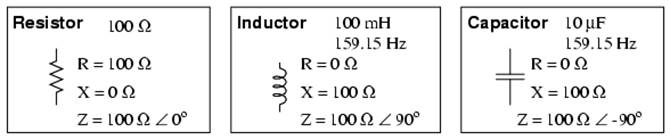
Perfect resistor, inductor, and capacitor.
The impedance phase angle for any component is the phase shift between voltage across that component and current through that component. For a perfect resistor, the voltage drop and current are always in phase with each other, and so the impedance angle of a resistor is said to be 0o. For an perfect inductor, voltage drop always leads current by 90o, and so an inductor's impedance phase angle is said to be +90o. For a perfect capacitor, voltage drop always lags current by 90o, and so a capacitor's impedance phase angle is said to be -90o.
Impedances in AC behave analogously to resistances in DC circuits: they add in series, and they diminish in parallel. A revised version of Ohm's Law, based on impedance rather than resistance, looks like this:
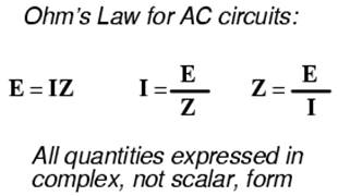
Kirchhoff's Laws and all network analysis methods and theorems are true for AC circuits as well, so long as quantities are represented in complex rather than scalar form. While this qualified equivalence may be arithmetically challenging, it is conceptually simple and elegant. The only real difference between DC and AC circuit calculations is in regard to power. Because reactance doesn't dissipate power as resistance does, the concept of power in AC circuits is radically different from that of DC circuits. More on this subject in a later chapter!
Series R, L, and C
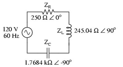
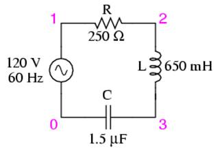
Let's take the following example circuit and analyze it: (Figure below)
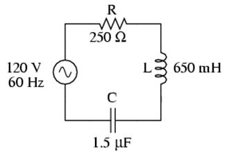
Example series R, L, and C circuit.
The first step is to determine the reactances (in ohms) for the inductor and the capacitor.
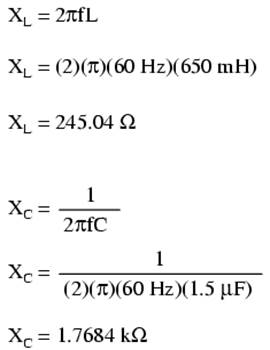
The next step is to express all resistances and reactances in a mathematically common form: impedance. (Figure below) Remember that an inductive reactance translates into a positive imaginary impedance (or an impedance at +90o), while a capacitive reactance translates into a negative imaginary impedance (impedance at -90o). Resistance, of course, is still regarded as a purely “real” impedance (polar angle of 0o):
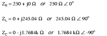
Example series R, L, and C circuit with component values replaced by impedances.
Now, with all quantities of opposition to electric current expressed in a common, complex number format (as impedances, and not as resistances or reactances), they can be handled in the same way as plain resistances in a DC circuit. This is an ideal time to draw up an analysis table for this circuit and insert all the “given” figures (total voltage, and the impedances of the resistor, inductor, and capacitor).
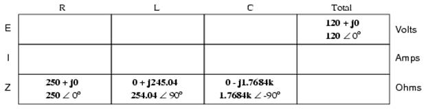
Unless otherwise specified, the source voltage will be our reference for phase shift, and so will be written at an angle of 0o. Remember that there is no such thing as an “absolute” angle of phase shift for a voltage or current, since it's always a quantity relative to another waveform. Phase angles for impedance, however (like those of the resistor, inductor, and capacitor), are known absolutely, because the phase relationships between voltage and current at each component are absolutely defined.
Notice that I'm assuming a perfectly reactive inductor and capacitor, with impedance phase angles of exactly +90 and -90o, respectively. Although real components won't be perfect in this regard, they should be fairly close. For simplicity, I'll assume perfectly reactive inductors and capacitors from now on in my example calculations except where noted otherwise.
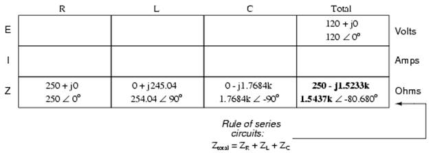
Since the above example circuit is a series circuit, we know that the total circuit impedance is equal to the sum of the individuals, so:
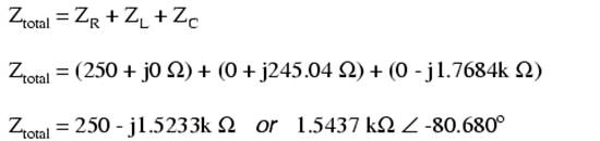
Inserting this figure for total impedance into our table:
We can now apply Ohm's Law (I=E/R) vertically in the “Total” column to find total current for this series circuit:
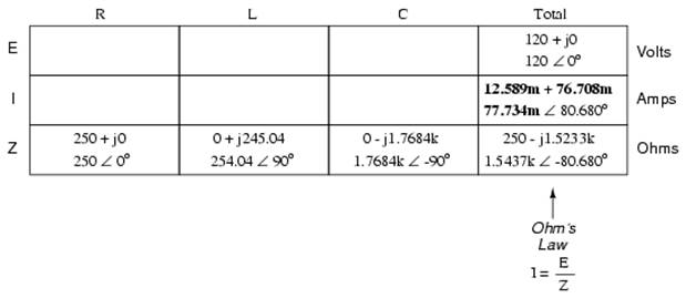
Being a series circuit, current must be equal through all components. Thus, we can take the figure obtained for total current and distribute it to each of the other columns:
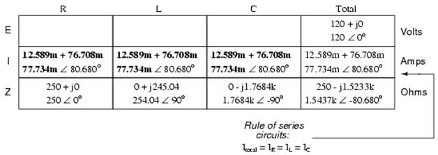
Now we're prepared to apply Ohm's Law (E=IZ) to each of the individual component columns in the table, to determine voltage drops:
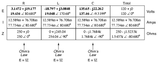
Notice something strange here: although our supply voltage is only 120 volts, the voltage across the capacitor is 137.46 volts! How can this be? The answer lies in the interaction between the inductive and capacitive reactances. Expressed as impedances, we can see that the inductor opposes current in a manner precisely opposite that of the capacitor. Expressed in rectangular form, the inductor's impedance has a positive imaginary term and the capacitor has a negative imaginary term. When these two contrary impedances are added (in series), they tend to cancel each other out! Although they're still added together to produce a sum, that sum is actually less than either of the individual (capacitive or inductive) impedances alone. It is analogous to adding together a positive and a negative (scalar) number: the sum is a quantity less than either one's individual absolute value.
If the total impedance in a series circuit with both inductive and capacitive elements is less than the impedance of either element separately, then the total current in that circuit must be greater than what it would be with only the inductive or only the capacitive elements there. With this abnormally high current through each of the components, voltages greater than the source voltage may be obtained across some of the individual components! Further consequences of inductors' and capacitors' opposite reactances in the same circuit will be explored in the next chapter.
Once you've mastered the technique of reducing all component values to impedances (Z), analyzing any AC circuit is only about as difficult as analyzing any DC circuit, except that the quantities dealt with are vector instead of scalar. With the exception of equations dealing with power (P), equations in AC circuits are the same as those in DC circuits, using impedances (Z) instead of resistances (R). Ohm's Law (E=IZ) still holds true, and so do Kirchhoff's Voltage and Current Laws.
To demonstrate Kirchhoff's Voltage Law in an AC circuit, we can look at the answers we derived for component voltage drops in the last circuit. KVL tells us that the algebraic sum of the voltage drops across the resistor, inductor, and capacitor should equal the applied voltage from the source. Even though this may not look like it is true at first sight, a bit of complex number addition proves otherwise:
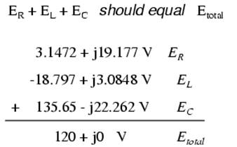
Aside from a bit of rounding error, the sum of these voltage drops does equal 120 volts. Performed on a calculator (preserving all digits), the answer you will receive should be exactly 120 + j0 volts.
We can also use SPICE to verify our figures for this circuit: (Figure below)
Example series R, L, and C SPICE circuit.
ac r-l-c circuit v1 1 0 ac 120 sin r1 1 2 250 l1 2 3 650m c1 3 0 1.5u .ac lin 1 60 60 .print ac v(1,2) v(2,3) v(3,0) i(v1) .print ac vp(1,2) vp(2,3) vp(3,0) ip(v1) .end |
freq v(1,2) v(2,3) v(3) i(v1) freq vp(1,2) vp(2,3) vp(3) ip(v1) |
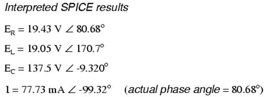
The SPICE simulation shows our hand-calculated results to be accurate.
As you can see, there is little difference between AC circuit analysis and DC circuit analysis, except that all quantities of voltage, current, and resistance (actually, impedance) must be handled in complex rather than scalar form so as to account for phase angle. This is good, since it means all you've learned about DC electric circuits applies to what you're learning here. The only exception to this consistency is the calculation of power, which is so unique that it deserves a chapter devoted to that subject alone.
REVIEW:
Impedances of any kind add in series: ZTotal = Z1 + Z2 + . . . Zn
Although impedances add in series, the total impedance for a circuit containing both inductance and capacitance may be less than one or more of the individual impedances, because series inductive and capacitive impedances tend to cancel each other out. This may lead to voltage drops across components exceeding the supply voltage!
All rules and laws of DC circuits apply to AC circuits, so long as values are expressed in complex form rather than scalar. The only exception to this principle is the calculation of power, which is very different for AC.
Parallel R, L, and C
We can take the same components from the series circuit and rearrange them into a parallel configuration for an easy example circuit: (Figure below)
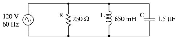
Example R, L, and C parallel circuit.
The fact that these components are connected in parallel instead of series now has absolutely no effect on their individual impedances. So long as the power supply is the same frequency as before, the inductive and capacitive reactances will not have changed at all: (Figure below)
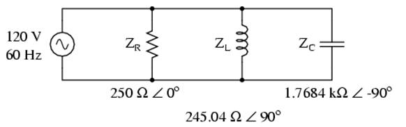
Example R, L, and C parallel circuit with impedances replacing component values.
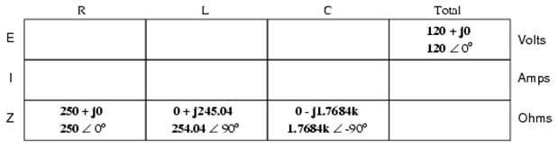
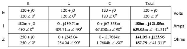
With all component values expressed as impedances (Z), we can set up an analysis table and proceed as in the last example problem, except this time following the rules of parallel circuits instead of series:
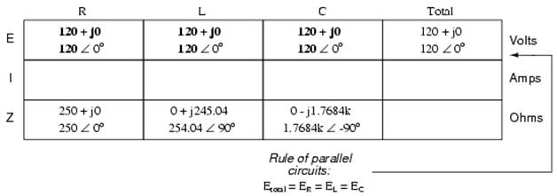
Knowing that voltage is shared equally by all components in a parallel circuit, we can transfer the figure for total voltage to all component columns in the table:
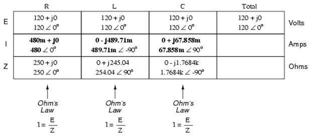
Now, we can apply Ohm's Law (I=E/Z) vertically in each column to determine current through each component:
There are two strategies for calculating total current and total impedance. First, we could calculate total impedance from all the individual impedances in parallel (ZTotal = 1/(1/ZR + 1/ZL + 1/ZC), and then calculate total current by dividing source voltage by total impedance (I=E/Z). However, working through the parallel impedance equation with complex numbers is no easy task, with all the reciprocations (1/Z). This is especially true if you're unfortunate enough not to have a calculator that handles complex numbers and are forced to do it all by hand (reciprocate the individual impedances in polar form, then convert them all to rectangular form for addition, then convert back to polar form for the final inversion, then invert). The second way to calculate total current and total impedance is to add up all the branch currents to arrive at total current (total current in a parallel circuit -- AC or DC -- is equal to the sum of the branch currents), then use Ohm's Law to determine total impedance from total voltage and total current (Z=E/I).
Either method, performed properly, will provide the correct answers. Let's try analyzing this circuit with SPICE and see what happens: (Figure below)
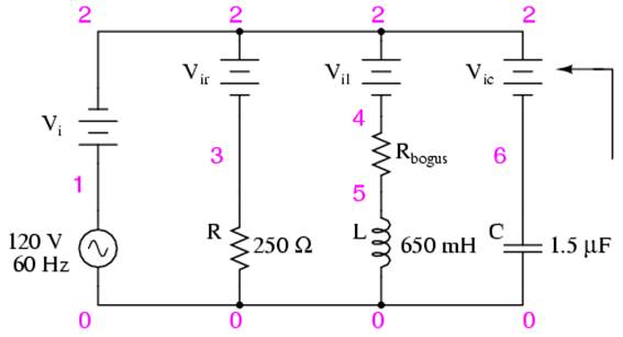
Example parallel R, L, and C SPICE circuit. Battery symbols are “dummy” voltage sources for SPICE to use as current measurement points. All are set to 0 volts.
ac r-l-c circuit |
freq i(vi) i(vir) i(vil) i(vic) freq ip(vi) ip(vir) ip(vil) ip(vic) |
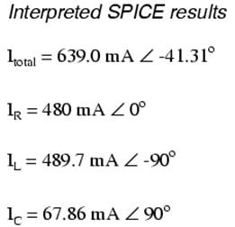
It took a little bit of trickery to get SPICE working as we would like on this circuit (installing “dummy” voltage sources in each branch to obtain current figures and installing the “dummy” resistor in the inductor branch to prevent a direct inductor-to-voltage source loop, which SPICE cannot tolerate), but we did get the proper readings. Even more than that, by installing the dummy voltage sources (current meters) in the proper directions, we were able to avoid that idiosyncrasy of SPICE of printing current figures 180o out of phase. This way, our current phase readings came out to exactly match our hand calculations.
Series-parallel R, L, and C
Now that we've seen how series and parallel AC circuit analysis is not fundamentally different than DC circuit analysis, it should come as no surprise that series-parallel analysis would be the same as well, just using complex numbers instead of scalar to represent voltage, current, and impedance.
Take this series-parallel circuit for example: (Figure below)
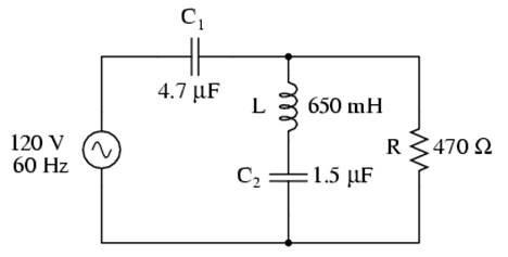
Example series-parallel R, L, and C circuit.
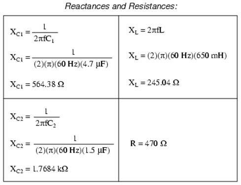
The first order of business, as usual, is to determine values of impedance (Z) for all components based on the frequency of the AC power source. To do this, we need to first determine values of reactance (X) for all inductors and capacitors, then convert reactance (X) and resistance (R) figures into proper impedance (Z) form:
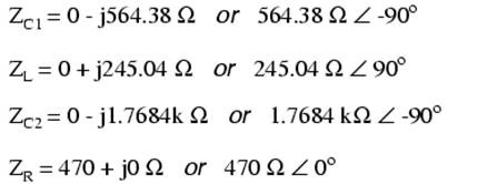
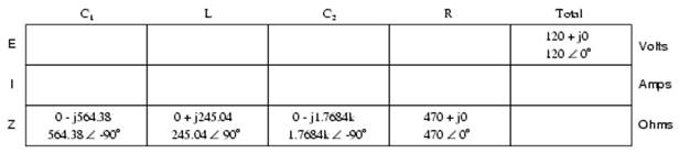
Now we can set up the initial values in our table:
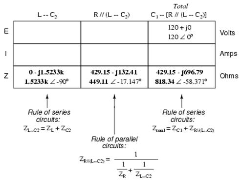
Being a series-parallel combination circuit, we must reduce it to a total impedance in more than one step. The first step is to combine L and C2 as a series combination of impedances, by adding their impedances together. Then, that impedance will be combined in parallel with the impedance of the resistor, to arrive at another combination of impedances. Finally, that quantity will be added to the impedance of C1 to arrive at the total impedance.
In order that our table may follow all these steps, it will be necessary to add additional columns to it so that each step may be represented. Adding more columns horizontally to the table shown above would be impractical for formatting reasons, so I will place a new row of columns underneath, each column designated by its respective component combination:
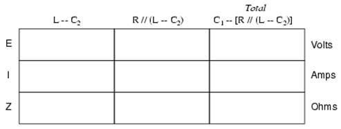
Calculating these new (combination) impedances will require complex addition for series combinations, and the “reciprocal” formula for complex impedances in parallel. This time, there is no avoidance of the reciprocal formula: the required figures can be arrived at no other way!
Seeing as how our second table contains a column for “Total,” we can safely discard that column from the first table. This gives us one table with four columns and another table with three columns.
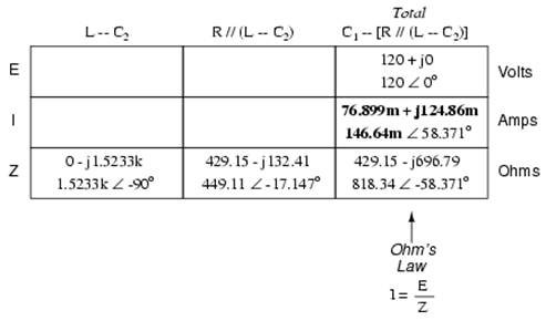
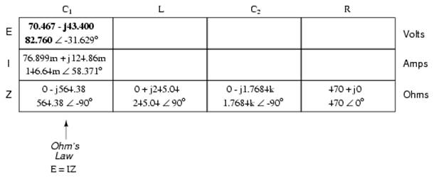
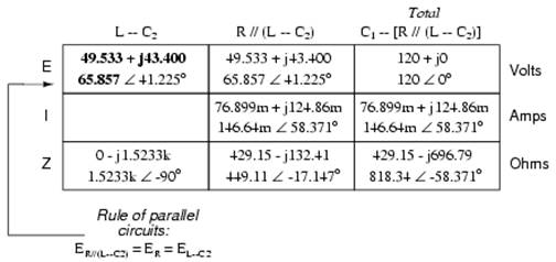
Now that we know the total impedance (818.34 Ω ∠ -58.371o) and the total voltage (120 volts ∠ 0o), we can apply Ohm's Law (I=E/Z) vertically in the “Total” column to arrive at a figure for total current:
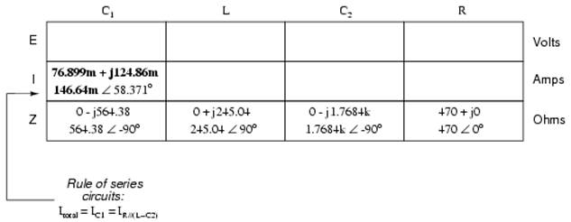
At this point we ask ourselves the question: are there any components or component combinations which share either the total voltage or the total current? In this case, both C1 and the parallel combination R//(L--C2) share the same (total) current, since the total impedance is composed of the two sets of impedances in series. Thus, we can transfer the figure for total current into both columns:
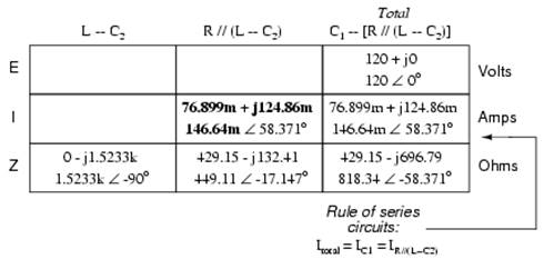
Now, we can calculate voltage drops across C1 and the series-parallel combination of R//(L--C2) using Ohm's Law (E=IZ) vertically in those table columns:
A quick double-check of our work at this point would be to see whether or not the voltage drops across C1 and the series-parallel combination of R//(L--C2) indeed add up to the total. According to Kirchhoff's Voltage Law, they should!
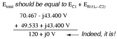
That last step was merely a precaution. In a problem with as many steps as this one has, there is much opportunity for error. Occasional cross-checks like that one can save a person a lot of work and unnecessary frustration by identifying problems prior to the final step of the problem.
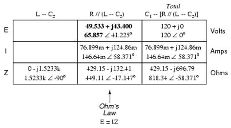
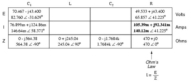
After having solved for voltage drops across C1 and the combination R//(L--C2), we again ask ourselves the question: what other components share the same voltage or current? In this case, the resistor (R) and the combination of the inductor and the second capacitor (L--C2) share the same voltage, because those sets of impedances are in parallel with each other. Therefore, we can transfer the voltage figure just solved for into the columns for R and L--C2:
Now we're all set for calculating current through the resistor and through the series combination L--C2. All we need to do is apply Ohm's Law (I=E/Z) vertically in both of those columns:
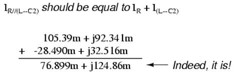
Another quick double-check of our work at this point would be to see if the current figures for L--C2 and R add up to the total current. According to Kirchhoff's Current Law, they should:
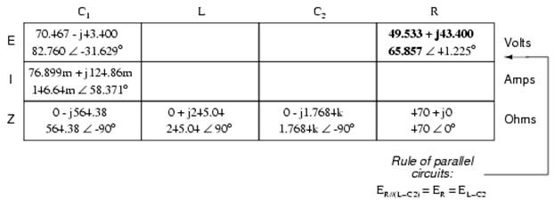
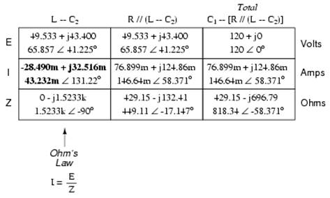
Since the L and C2 are connected in series, and since we know the current through their series combination impedance, we can distribute that current figure to the L and C2 columns following the rule of series circuits whereby series components share the same current:
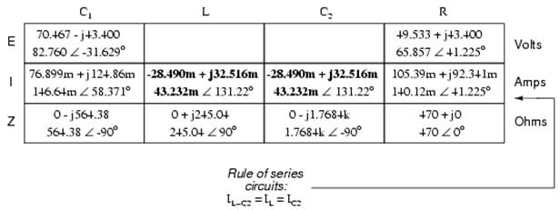
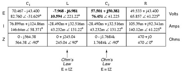
With one last step (actually, two calculations), we can complete our analysis table for this circuit. With impedance and current figures in place for L and C2, all we have to do is apply Ohm's Law (E=IZ) vertically in those two columns to calculate voltage drops.
Now, let's turn to SPICE for a computer verification of our work:
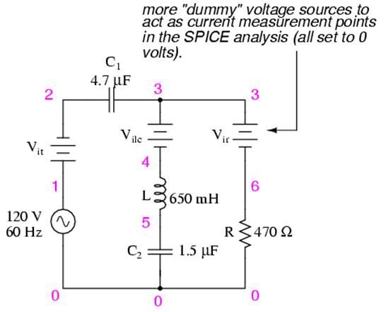
Example series-parallel R, L, C SPICE circuit.
ac series-parallel r-l-c circuit v1 1 0 ac 120 sin vit 1 2 ac 0 vilc 3 4 ac 0 vir 3 6 ac 0 c1 2 3 4.7u l 4 5 650m c2 5 0 1.5u r 6 0 470 .ac lin 1 60 60 .print ac v(2,3) vp(2,3) i(vit) ip(vit) .print ac v(4,5) vp(4,5) i(vilc) ip(vilc) .print ac v(5,0) vp(5,0) i(vilc) ip(vilc) .print ac v(6,0) vp(6,0) i(vir) ip(vir) .end |
freq v(2,3) vp(2,3) i(vit) ip(vit) C1 |
freq v(4,5) vp(4,5) i(vilc) ip(vilc) L |
freq v(5) vp(5) i(vilc) ip(vilc) C2 |
freq v(6) vp(6) i(vir) ip(vir) R |
Each line of the SPICE output listing gives the voltage, voltage phase angle, current, and current phase angle for C1, L, C2, and R, in that order. As you can see, these figures do concur with our hand-calculated figures in the circuit analysis table.
As daunting a task as series-parallel AC circuit analysis may appear, it must be emphasized that there is nothing really new going on here besides the use of complex numbers. Ohm's Law (in its new form of E=IZ) still holds true, as do the voltage and current Laws of Kirchhoff. While there is more potential for human error in carrying out the necessary complex number calculations, the basic principles and techniques of series-parallel circuit reduction are exactly the same.
REVIEW: Analysis of series-parallel AC circuits is much the same as series-parallel DC circuits. The only substantive difference is that all figures and calculations are in complex (not scalar) form. It is important to remember that before series-parallel reduction (simplification) can begin, you must determine the impedance (Z) of every resistor, inductor, and capacitor. That way, all component values will be expressed in common terms (Z) instead of an incompatible mix of resistance (R), inductance (L), and capacitance (C). |
Author : not indicated on the source document of the above text
If you are the author of the text above and you not agree to share your knowledge for teaching, research, scholarship (for fair use as indicated in the United States copyrigh low) please send us an e-mail and we will remove your text quickly.
Electronics components notes
If you want to quickly find the pages about a particular topic as Electronics components notes use the following search engine:
Electronics components notes
Please visit our home page
Larapedia.com Terms of service and privacy page