Electrical Measurements introduction
Electrical Measurements introduction
The following texts are the property of their respective authors and we thank them for giving us the opportunity to share for free to students, teachers and users of the Web their texts will used only for illustrative educational and scientific purposes only.
All the information in our site are for educational uses.
The information of medicine and health contained in the site are of a general nature and purpose which is purely informative and for this reason may not replace in any case, the council of a doctor or a qualified entity legally to the profession.
Electrical Measurements introduction
Phys 2212L Introduction: Electrical Measurements
Here follows some reference information on the electronic instruments used in our physics laboratories. Electrical symbols and codes are also listed for your reference. You should familiarize yourself with the relevant sections before attempting to perform the experiments.
The following subjects are discussed:
- Circuit Diagrams
- Resistor Color Codes
- Digital Multimeter (DMM)
- Oscilloscope
- Signal Generator
Circuit Diagrams or Schematics
An electric circuit consists of three things:
1. A source of electrical power;
2. One or more resistors or other circuit components that use the power;
3. Wires or leads that provide one or more paths from the power source, through the components, and back to the power source.
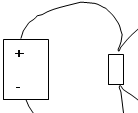
A circuit diagram or schematic is an idealized representation of an electric circuit. The diagram is much simpler and easier to follow than the physical circuit, where wires, instruments and a variety of connections can confuse the eye. What is important in circuit diagrams (and in the actual circuit) is what connects to what, not how long the wires are or the physical appearance of the circuit components.
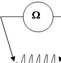
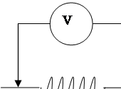
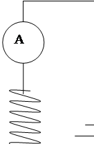
For instance, the first two drawings below depict the same circuit: two resistors connected in parallel across a power source. The third diagram is a schematic for both.
The most commonly used circuit symbols are listed in Table 1.
Symbol |
Description |
|
|
Wire; often called a lead. What matters with leads is where they are connected, not how long they are or what shape they take.
|
|
|
Switch in open position.
|
|
|
Direct current (DC) voltage source. This can be a battery or a power supply. The plus/minus signs are not part of the symbol. |
|
|
Resistor. A resistor is any component or combination of components that draws power from the voltage source. An appliance such as a toaster is just a set of resistors.
|
|
|
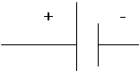
Capacitor. This is a device that stores electric charge. |
|
|
Inductor. Used in alternating current (AC) circuits.
|
|
|
|
Meters: Ammeter; Voltmeter.
A multimeter can be either an ammeter or a voltmeter, depending on its setting.
|


|
An AC power source. A signal generator, aka function generator, is an AC power source that can deliver power at various frequencies. |
|
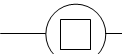
An oscilloscope. Oscilloscopes are used to measure the amplitude and frequency of a time varying voltage. |

Resistor Color Codes
Resistors are often coded with colored bands to designate their resistance values, in ohms.
- The first two bands represent the first two digits in the value.
- The third band is a multiplier, in powers of ten. Multiplying the first two digits by the appropriate power of ten gives the resistance value.
- The fourth band represents the tolerance, or uncertainty in the resistance value.
The codes are listed in Table 2.
Table 2: Resistor Color Codes
Color |
Value |
Black |
0 |
Brown |
1 |
Red |
2 |
Orange |
3 |
Yellow |
4 |
Green |
5 |
Blue |
6 |
Violet |
7 |
Gray |
8 |
White |
9 |
Silver |
10 % |
Gold |
5 % |
Digital Multimeter (DMM) & Electrical Measurements
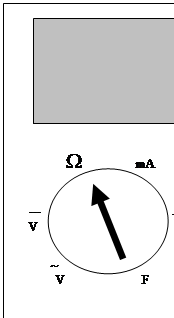
A multimeter can perform a variety of electrical measurements. A digital multimeter displays the measurement digitally (rather than by a needle). The type of measurement to be performed is selected by setting a dial on the meter:
When the dial is set to The meter operates as a
W (ohms -resistance) Ohmmeter
V (VDC) Voltmeter, direct current
V (VAC) Voltmeter, alternating current
A (ADC) Ammeter, direct current
A (AAC) Ammeter, alternating current
F Capacitance meter
L Inductance meter
Some meters can also measure temperature (°C or °F). A tilde (~) is often used to represent AC measurements; a dashed bar (---) represents DC measurements.
Refer to Table 3 for the procedures to use in taking measurements.
Digital Multimeter
Table 3: DMM Measurements
Resistance
Element to be measured should be removed from the circuit.
|
|
Voltage
Measure voltage by connecting the voltmeter across a circuit or circuit element. The voltmeter will measure the potential difference between the two points to which it is connected.
|
Important: Be certain that the DMM is set to DCV before you connect to the circuit. If the DMM is set to A (Amperes) or mA (milli-Amperes) when you connect as for a voltmeter, you will blow a fuse in the meter. You may also burn out the meter completely.
|
Current
The ammeter is inserted into the circuit to measure current.
NOTE: When measuring high currents (above 5 A), do not leave the meter connected for more than 10 seconds. Prolonged currents can burn out the meter. |
Important: Disconnect the meter quickly if an overload (“0L”) condition is displayed. This means the current is too high for the range and the fuse will soon blow.
|
Capacitance |
|
Inductance
|
|
Design of the DMM
Selecting the voltmeter function on the DMM selects an internal circuit that includes a very high resistance. This prevents any appreciable current from taking this alternate path around the circuit element that is being measured. In this way, the original current in the circuit is not disturbed.
On the other hand, setting the DMM to ammeter selects a very low internal resistance. In this way, the meter causes a negligible voltage drop when it is inserted in the circuit. Again, the original current in the circuit is not disturbed.
Incorrect settings
What happens when the DMM is set incorrectly?
Situation |
Result |
DMM set to voltmeter, inserted in series in the circuit (as for an ammeter) |
|
DMM set to ammeter, connected across the circuit or circuit element (as for a voltmeter)
|
Current takes the path of least resistance:
|
The morale of the story:
|
Pay attention!
|
Oscilloscope: Voltage and Frequency Measurements
The Oscilloscope is a device used to measure the frequency and amplitudes of electrical signals. It is useful as a voltmeter for voltages that vary with time (alternating current voltages).
The heart of the scope is a cathode ray tube (CRT). In a CRT, a beam of electrons generated at the back of the tube is directed against a phosphorescent screen at the front. The screen glows at the point it is struck by the electron beam (see Diagrams below).
The beam electrons are subject to two independent voltages: an internal voltage applied in the horizontal direction and an external voltage (the one to be measured) applied in the vertical direction.
The internal voltage is generated by the scope and determines where the electron beam will hit the screen horizontally. Its amplitude and polarity are timed so that the beam hits the screen starting at the left and then “sweeps” across the screen to the right. It is thus called the “sweep voltage” and the sweep setting on the scope controls the timing of the sweep.
The voltage to be measured is applied in the vertical direction, across the top and bottom of the CRT. This voltage makes the electron beam veer up or down, depending on the polarity and strength of the voltage. The stronger the voltage, the more the beam veers. Thus the vertical displacement of the trace on the screen is a measure of the amplitude of the input voltage.
The combination of these two voltages creates the trace pattern we see on the screen. If the input voltage is sinusoidal, the trace will also be a sine wave.
How the Oscilloscope Works
1. An electron beam is generated at the rear of the CRT. (The beam
is indicated by the arrow in the diagram at right.) The beam hits
the phosphorescent screen at the front of the CRT, making it glow.
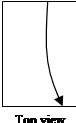
2. An internally-generated “sweep” voltage applied horizontally makes
the beam sweep across the screen left to right. The frequency of the
sweep is controlled by the frequency knob on the scope.
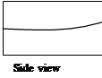 3. The voltage to be measured is applied vertically. This makes
the beam swerve up or down, according to the strength and
polarity of the applied voltage.
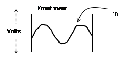
The Result:
Oscilloscope Setup
Step |
Normal (default) settings |
Alternate settings/Explanation |
1. |
Power: On |
|
2. |
Channel 1: Connect a BNC connector to the input post.
Channel 2: To display two traces at once, connect another BNC to the Channel 2 input.
|
Connect the leads from the signal(s) you want to display to the BNC connector(s).
|
3. |
AC-Gnd-DC switch: DC. |
AC: Subtract out any DC components of the signal. Gnd: Displays a ground trace (a flat line). DC: Displays the signal as is. We will always set this to DC, even for AC circuits.
|
4. |
Trig Level: Midrange |
This sets the threshold voltage for the scope to begin its internal sweep. Adjust this if the trace is unstable.
|
5. |
Coupling: Auto |
Auto: For frequencies > 10 hz. Norm: For frequencies < 10 hz.
|
6. |
Source: Ch 1 |
Determines which signal the scope uses to time its sweep. Set this to the primary signal you are looking at.
|
7. |
Holdoff: Midrange Knob pushed in.
|
Adjust this if the trace runs. Also try Trig Level.
Knob out: This puts the scope in Chop mode. (Use Chop to display dual trace at low frequencies.)
|
8. |
Vert Mode: Ch 1 |
Ch1: Displays Channel 1. Ch 2: Displays Channel 2. Dual: Displays both channels at once. Add: Displays the sum of the two signals.
|
9.
|
Volt/Div: 2 volts per division. |
This controls the vertical (voltage) scale of the scope display. A “division” is the space between the grid lines (vertically).
Each channel has its own knob.
|
10. |
Calibration knob (voltage): Full clockwise.
|
This varies the vertical (voltage scale) calibration. Always set this to “calibrated”. |
11. |
Time/Div: 2 mS (milliseconds) per division.
|
This controls the sweep rate of the electron beam and sets the horizontal (time) scale of the scope display. A “division” is the space between the grid lines (horizontally).
|
12. |
Calibration knob (time): Full clockwise.
|
This varies the horizontal (time scale) calibration. Always set this to “calibrated”. |
13. |
Vertical Position: Midrange. Knob pushed in. |
Adjust this to vary the position of the trace. Each channel has its own knob.
Knob out: Alt mode. Alternates triggering between the two channels. Use for dual trace display if one or both traces become unstable.
|
14. |
Horizontal Position: Midrange |
Adjust this to vary the position of the trace. Each channel has its own knob.
|
The Function Generator
The Function Generator (aka Signal Generator, SG) is a device that outputs a time-varying EMF. The frequency of its output voltage can be set by the user. This makes it useful as a power source for alternating current (AC) circuits, or any time a variable voltage is desired.
We usually use an oscilloscope in conjunction with an SG, so that we can measure its output. Always Remember: The SG generates the signal. The scope just displays it. To change the signal, adjust the SG; to change the display, adjust the scope.
Function Generator Setup
|
Digital Function Generator(PASCO)
|
Function Generator(Global Specialties) |
1. |
Plug in the power cord and turn on the device.
|
Plug in the power cord and turn on the device. The on-off switch is on the back. |
2. |
Amplitude: midrange
|
Range: 1-10 V
Use the “Fine” knob to adjust the output in the experiment. |
3. |
|
DC Offset: Off
|
4. |
Function switch: Start with sine-wave output to set up the scope.
Switch to square wave in the RC Circuits experiment.
|
Function switch: Start with sine-wave output to set up the scope.
Switch to square wave in the RC Circuits experiment.
|
5. |
Range: 1-100 Hz |
Freq Mult (frequency multiplier): 10
|
6. |
Frequency: 60 hertz
A good place to get set-up. Adjust this knob as needed in the experiment. |
Freq (frequency): 6
This gives a starting frequency of 60 hertz – a good place to get set up. Later, you will adjust these knobs as needed.
|
7. |
Plug banana wires into the LOW and the GND plugs. Connect these leads to the circuit, or to the scope. |
Connect a BNC connector to the output plug. Plug two banana wires into the BNC. Connect these leads to the circuit, or to the scope.
Note that the output on this model has a 600 W impedance (resistance). You must include this in the total resistance in the circuit.
|
Source : http://depts.gpc.edu/~dunpslb/2212L/Cspk2212L/00EM.doc
Web site link: http://depts.gpc.edu/~dunpslb/2212L/Cspk2212L/
Google key word : Electrical Measurements introduction file type : doc
Author : not indicated on the source document of the above text
If you are the author of the text above and you not agree to share your knowledge for teaching, research, scholarship (for fair use as indicated in the United States copyrigh low) please send us an e-mail and we will remove your text quickly.
Electrical Measurements introduction
If you want to quickly find the pages about a particular topic as Electrical Measurements introduction use the following search engine:
Electrical Measurements introduction
Please visit our home page
Larapedia.com Terms of service and privacy page