Principles of Hydraulics
Principles of Hydraulics
The following texts are the property of their respective authors and we thank them for giving us the opportunity to share for free to students, teachers and users of the Web their texts will used only for illustrative educational and scientific purposes only.
All the information in our site are given for nonprofit educational purposes
The information of medicine and health contained in the site are of a general nature and purpose which is purely informative and for this reason may not replace in any case, the council of a doctor or a qualified entity legally to the profession.
Principles of Hydraulics
Hydraulics is a branch of engineering that deals with the practical application of water or other liquids at rest or in motion. The two major divisions of hydraulics are hydrostatics and hydrodynamics.
Hydrostatics
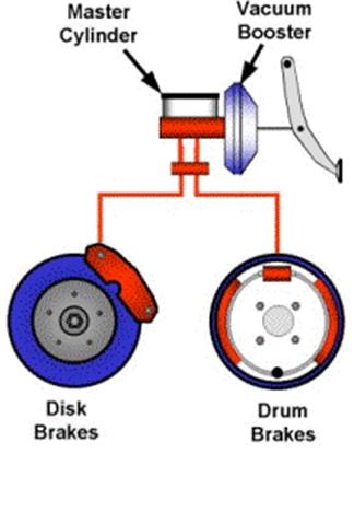
Hydrostatics is the study of liquids at rest and the forces exerted on them or by them. Equilibrium is the condition when all forces and torques are balanced by equal and opposite forces and torques. Most hydraulic systems apply hydrostatic principles. For example, the fluid in a automotive braking system is at rest and the pressure throughout the system is in equilibrium. The brake system is activated by applying pressure to the foot pedal. The fluid in the system transmits the applied force from the foot pedal to the slave cylinder piston. The slave cylinder piston transmits the force to brake pad which applies pressure to the brake drum (rear wheel on newer vehicles). The pressure is equal in all parts of the system, but higher than the pressure of the fluid when the system is at rest.
Simplified auto brake system
 Hydrodynamics
Hydrodynamics is the study of force exerted on a solid body by the motion or pressure of a fluid. For example, fluids are transferred through a non-positive displacement pump by angular velocity. A non-positive displacement pump is a pump that is not sealed between its inlet and outlet. Angular velocity forces are produced by a rotating object. The fluid is force to the discharge (outlet) port by rotating impeller blades. The output of the pump may be reduced or completely blocked if the pressure of the discharge circuit is increased because there is no positive displacement of fluid.
Hydrodynamic pump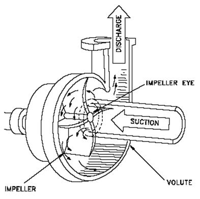 , non-positive displacement pump
Hydraulic History (abbreviated)
 Early hydraulic systems consisted of diverting streams for village irrigation and water supply and digging wells. There exists evidence of hydraulic principle use in early Mesopotamia (currently geography encompassed by Iraq). This record predates the existence of Christianity by over a thousand years. One of the first recorded machines for hydrostatic use is the Archimedes water-screw. Developed by the Greek Archimedes, it believed that earlier Egyptian technology influenced the development of this invention.
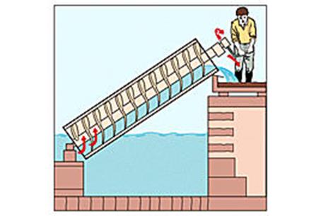
Archimedes screw, a spiral screw turned inside
a cylinder, was once commonly used to lift water
from canals. The screw is still used to lift water in
the Nile delta in Egypt, and is often used to
shift grain in mills and powders in factories.
Liquid Characteristics
In hydraulics the term fluid refers to gases as well as liquids. A fluid is a substance that tends to conform to the outline or shape of its container (such as a liquid or gas). Fluids yield easily to pressure. A liquid is a fluid that can flow readily and assume the shape of its container. Fluids have no independent shape but do have a definite volume. Liquids do not expand indefinitely and are only slightly compressible. A gas is a fluid that has neither independent shape nor volume and tends to expand indefinitely. Oxygen, hydrogen, nitrogen, etc. are gases.
Liquids make convenient fluids for transmitting force because they are not highly compressible like gases. The term fluid is used in reference to a liquid because liquids are specifically used in hydraulic systems. Work produced in a hydraulic system is dependent on the pressure and flow of the fluid in the system.
Transmission of Hydraulic Force
 To understand the principals of hydraulics it is necessary to understand Blaise Pascal’s theorem upon which all hydraulics are based. Pascal realized that enclosed fluids under pressure follow a definite law. Pascal’s theorem is now stated as a law of physics; pressurized fluid within a closed container—such as a cylinder or pipe—exerts equal force on all surfaces of the container and is the same in every direction. Force is the energy that produces movement. Although this law and its potential for technology were realized in the 17th century, it was not until the 20th century that fluid power became a means of energy transmission.
Pascal’s law of equal pressure
of enclosed fluids on all surfaces
in all directions
Pressure
Pressure is the force per unit area. Pressure is expressed as atmospheric, gauge and absolute. Atmospheric pressure is the force exerted by the weight of the atmosphere (air) on the Earth’s surface. The weight of the atmosphere, acting over a height of several hundred thousand feet above the Earth’s surface varies slightly with weather conditions and variation in gravity. For practical purposes and to establish a standard for weight of the atmosphere at sea level is determined to be 14.7 pounds per square inch (psi). Atmospheric pressure is expressed in psi and is measured with a mercury barometer. A mercury barometer is an instrument that measures atmospheric pressure using a column 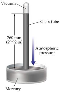 of mercury.
Torricelli’s Mercury Barometer
A mercury barometer consists of a glass tube that is closed on one end and completely filled with mercury. The tube is inverted and the open end is submerged in a dish of mercury. A vacuum (low pressure) is created at the top of the tube as the mercury tries to run out of the tube. Vacuum is a pressure lower than atmospheric pressure. The pressure of the atmosphere on the mercury in the open dish prevents the mercury in the tube from running out of the tube. The height of the mercury in the tube corresponds to the pressure of the atmosphere on the mercury in the open dish.
A mercury barometer is commonly calibrated in inches of mercury (in. Hg). At sea level, the atmosphere can support 29.92” Hg in the tube. A barometric pressure of 29.92” equals one atmosphere or 14.7 psi. Pressures above one atmosphere are generally expressed in psi and pressures below one atmosphere are generally expressed in in. of Hg. Minute pressure changes are expressed in inches of water column (in.WC). Atmospheric pressure at sea level should be able to hold water in a column 33.9’ (407.37”) high because atmospheric pressure is able to hold mercury in a column 29.92” high and water is 13.6 times lighter than mercury.
Gauge pressure is pressure above atmospheric pressure that is used to express pressure inside a closed system. Gauge pressure assumes that atmospheric pressure is zero (0 psi). Most pressures are measured as gauge pressure unless otherwise specified. Gauge pressure is expressed in pounds per square inch (psig).
Absolute pressure is pressure above a perfect vacuum. Absolute pressure is the sum of gauge pressure plus atmospheric pressure. Absolute pressure is expressed in pounds per square inch absolute (psia).
Pressure outside a closed system (such as normal air pressure) is expressed in pounds per square inch absolute. The difference between gauge pressure and absolute pressure is the pressure of the atmosphere at standard conditions (14.7psi). A pressure gauge reads 0 psi at normal atmospheric pressure. To find absolute pressure when gauge pressure is known, the atmospheric pressure of 14.7 psi is added to the gauge pressure. Absolute pressure is found by applying the formula:
psia = psig + 14.7
Where
psia = pounds per square inch absolute
Psig = pounds per square inch gauge
14.7 = constant (atmospheric pressure at standard conditions)
Pressure other than atmospheric pressure is considered to be artificial and is produced to transfer or amplify force in hydraulic systems. This transferred or amplified force is used to do work such as lifting a car with a hydraulic jack, running a conveyor with a hydraulic motor, or stamping steel in automotive components.
Area, force and pressure are the basis of all hydraulic systems. The force exerted by a liquid is based on the size of the area on which the liquid pressure is applied. In hydraulic systems this area usually refers to the face of the piston, which is circular in shape. Area is always expressed in square units such as sq. in. or sq. mm.
A circle with a diameter the same as a square has less area. The area of a circle is exactly 78.54% of the area of a square with the same measurements.
The area of a piston can be found if the force and pressure applied to a cylinder is known. The applied pressure on a piston can be found if the amount of force and the piston area are known. Also the force produced by a piston can be found if the area and pressure applied to a piston are known. Two of the values must be known to find the unknown value.
The relationship between force, pressure and area can be recalled using the force, pressure, and area formula pyramid from the standard calculations handout sheet.
By covering the letter of the unknown value, the formula for finding the solution is shown.
 Head pressure
Head is the difference in the level liquid (fluid) between two points. Head is expressed in feet. Head pressure is the pressure at any point below the surface of the fluid.
In an open cylinder, the pressure of the fluid at any depth in the cylinder is proportional to the height of the column of fluid. The pressure in a column of fluid is determined by the columns height and the fluid’s weight, not the shape of the vessel. The pressure at the same level in each vessel is identical if the pressure surrounding the different surrounding the different-shaped vessels is the same and the fluid in each vessel is the same. The pressure of the fluid at any level in a vessel is based on the height of the fluid above that level and is the same at that level regardless of the shape of the vessel.
In a hydraulic system, head pressure is the energy or pressure that supplies a hydraulic pump. Atmospheric pressure and head pressure combine to feed the intake (suction) line connecting a hydraulic pump to a reservoir.
Head is classified as static or dynamic. Static head is the height of a fluid above a given point in column at rest. Static head pressure is a force over and area created by the weight of the fluid itself. Static head pressure is potential energy. The pressure of water per foot of static head is calculated by using .0361 lb/cu in. or 2.31’ head of water for each psi.
Dynamic head is the head of a fluid in motion. Dynamic head represents the pressure necessary to force a fluid from a given point to a given height. Dynamic head pressure is the pressure and velocity of a fluid produced by a liquid in motion. Dynamic head pressure results when a valve is opened and fluid is allowed and open flow. Dynamic head pressure may be used to direct an open flow of fluid. For example, dynamic head pressure was used in early prospecting days to wash away the sides of mountains to retrieve gold. This was accomplished by piping water from higher lakes and using dynamic head pressure to produce a high pressure and high velocity.
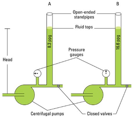
Hydrostatic head. The fluid height in
columns A and B is identical, but the
pressure reading on the gauges
differs because of the different fluid
densities. Hydrostatic head refers to
the vertical column height;
hydrostatic pressure refers to the
force exerted by the fluid.
Flow
Fluid flow is the movement of fluid caused by a difference in pressure between two points. In a hydraulic system, fluid flow is produced by the action of a pump and expressed as a measurement of gallons per minute (gpm) or liters per minute (lpm). Fluid flow in a hydraulic system is affected by friction and the viscosity of the fluid. Fluid flow is based on the volume and capacity of the system and the velocity of the fluid in the system. Fluid flow also affects the speed of a hydraulic system. In a system with flowing fluid, pressure is caused by total resistance to fluid flow from a pump. Pressure results only when there is resistance to flow. Resistance to flow is comprised of friction throughout the system and actuator loads. A pressure change occurs to a fluid due to its flow is generally expressed in psi.
Friction
Friction is generated throughout a hydraulic system between the piping wall and the fluid, and within the fluid as fluid layers slide by one another. The faster the fluid flows, the greater the friction. Any friction generated becomes a resistance to fluid flow. Pressure must be increased to overcome the friction. Each component in a hydraulic system offers resistance and reduction of available working pressure.
A fluid flows because of a difference in pressure. The pressure of a moving fluid is always higher upstream. Pressure drop is the pressure differential between upstream and downstream fluid flow cause by resistance. The pressure developed in a hydraulic system is designed to be used as hydraulic leverage. Pressure and fluid flow are independent of each other, but both assist in the output. Pressure provides the force and flow rate is used to provide speed. Flow rate is expressed in gpm and is typically determined by the capacity of the pump.
Fluids follow the path of least resistance. For example, a hydraulic system consisting of a telescoping cylinder for lifting purposes will extend the largest portion first. Force = pressure times area determines which section of the cylinder will extend first. The larger area of the telescope’s base cylinder will provide greater lifting power for a given pressure, and will extend initially. The larger force from the base cylinder area begins to move the weight as a lighter resistance compared to the other cylinders smaller area.
 Fluid flow in a telescoping cylinder
Volume
Volume is the three-dimensional size of an object measured in cubic units. Regardless of the shape of the figure, volume is expressed in cubic units (cu in., cu ft, mm3, m3, etc.). The volume of a figure is found by calculating the area of the figure and multiplying by the length. The volume of a cylinder is found by applying the procedure:
Find the area of cylinder.
A = .7854 x D2
Where
A = area (in sq units)
.7854 = constant
D2 = diameter squared
Find volume of cylinder.
V = A x L
Where
V = volume
A = area (in square units)
L = length (in units)
Capacity
Capacity is the ability to hold or contain something. Capacity is expressed in cubic units and is calculated from a containers volume. Fluids are measured in ounces, pints, quarts, gallons, liters, etc.
Fluid measurements can also be expressed in cubic units (cu in., cu ft, etc.) because fluids occupy three dimensions. For example, one gallon of fluid equals 231 cu in.
The quantity of fluid required to fill a specific volume is determined by calculating the volume and dividing by 231.
Less hydraulic fluid is required to retract a piston than is required to extend a piston. This is due to the rod taking up part of the cylinder volume (reduced capacity). The volume that the piston rod occupies must be subtracted from the total volume of the cylinder when determining the volume of fluid that a cylinder displaces when retracting.

Single acting cylinder. Deduct the volume of the rod from the total cylinder volume to determine fluid capacity of rod end.
Velocity
Velocity is the distance a fluid travels in a specified time. Velocity generally means the change in position of a fluid particle during a certain time interval. This may be represented as a distance in feet per second (ft/sec).
Velocity is measured as a vector. A vector is a quantity that has a magnitude and direction. A vector is commonly represented by a line segment whose length represents its magnitude and whose orientation represents its direction.
The velocity of a fluid particle is determined by subtracting it’s initial position from its final position and dividing by the value of value of the initial time subtracted from the final time. Velocity is found by applying the equation:
V = x2 – x1
t2 – t1
Where
V = velocity (in ft/sec)
x2 = final position (in ft)
x1 = initial position (in ft)
t2 = final time (in sec)
t1 = initial time (in sec)
The velocity of the hydraulic fluid in a system should not exceed recommended values because turbulent conditions result with loss of pressure and excessive heating. The concept for predicting turbulence (non laminar flow) is based upon the Reynolds number. More about Reynolds numbers and their calculation will be covered in later lessons.
Flow Rate
Flow is the movement of fluid. Flow rate is the volume of fluid flow. A fluid in motion is always flowing but its rate of flow may change. Fluid velocity depends on the rate of flow in gallons per minute (gpm) and the cross-sectional area of a pipe or component.
The velocity of a fluid increases at any restriction in a pipe or component if the flow rate remains the same in the system. Common restrictions include valves, elbows, pipes, reducers, etc. Also the velocity of a fluid decreases as the cross-sectional area of a pipe or component increases.
The law of conservation of matter states that the mass or volumetric flow rate of an incompressible fluid through a pipe is constant at every point in the pipe. The velocity must increase at any restriction if there are no leaks in the system and the flow rate remains constant. The velocity increases four times to maintain a constant rate of flow, if the original pipe diameter is changed to one-half of its original size.
Speed
The speed of a cylinder rod is determined by volume, capacity, and fluid flow velocity. To determine the speed at which a cylinder rod moves, the flow rate at which hydraulic fluid is directed into the cylinder must be known.
The speed of a cylinder rod is independent of pressure (yup it’s true). The speed of rod extension is usually expressed in inches per minute (in. /min). The speed of rod extension is directly proportional to the flow rate.
Two methods of increasing speed at which a load (or cylinder rod) in a hydraulic system moves are by using a smaller diameter cylinder or by increasing the rate of fluid flow to the cylinder. A small diameter cylinder produces an increase in speed and a decrease in applied force as compared to a larger cylinder. Two cylinders of different diameters having the same length have different fluid capacities and if both receive the same rate of fluid flow, the rate of travel and pressure output are different.
Flow rate must be kept below
the rate at which turbulence
occurs in the system, derived by
the calculation of a Reynolds
number
Mechanical Advantage
Mechanical advantage is the ratio of the output force of a device to the input force. Mechanical advantage is achieved when an applied force is multiplied, resulting in a larger output force. Devices that produce mechanical advantage include levers, block and tackles, gears etc.
Mechanical advantage results from a force applied a certain distance from a fulcrum. A fulcrum is a support on which a lever turns or pivots and is located somewhere between the effort force and the resistance force. In determining the force needed to balance a lever/fulcrum mechanism, the effort force must be farther from the fulcrum than the resistance force or must have and effort force equal to or greater than the resistance force.
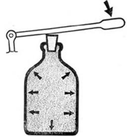
Pascal’s law states that pressure exerted on enclosed fluid is transmitted undiminished in every direction. This is demonstrated by a fluid filled bottle. As a cork is pressed further into the bottle, the pressure throughout the bottle is increases until the incompressible fluid bursts the bottle. The bottle bursts because the force applied to one area (the cork) is equal to the pressure multiplied by the larger area (the body of the bottle). The resulting force within a vessel is a product of the input force and the input pressure area divided by the output pressure area.
Fluids are well suited for being transmitted through pipes, hoses and passages because of these force characteristics. This force is energy, which can produce movement, work, or leverage when applied to a hydraulic application. For example, interconnected hydraulic cylinders of different diameters produce hydraulic leverage in a typical hydraulic car jack.
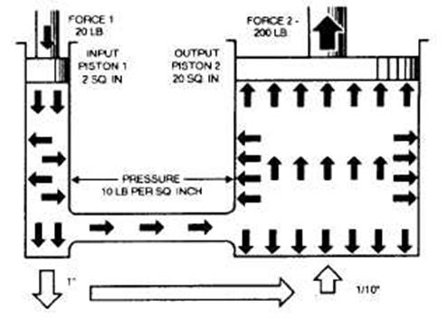
Force multiplication with interconnected cylinders of different sizes.
At times, system pressure must be determined before calculating either input force or the output force. This may be required when determining the input force required to produce a given output force with given size cylinders. The required input force is determined by calculating the area of the output cylinder, calculating the pressure in the system, and determining the input force based on the system pressure and area of the input cylinder.
Hydraulics is the branch of engineering that deals with the practical application of water or other liquids at rest or in motion. Hydrostatics is the study of fluids at rest and the forces exerted on them or by them. Hydrodynamics is the study of the forces exerted on a solid body by the motion or pressure of a fluid. A liquid is a fluid that can flow readily and assume the shape of its container. Fluid flow is the movement of fluid caused by a difference in pressure between two points. In a hydraulic system, fluid flow is produce by the action of a pump and is expressed as a measurement of gallons per minute or liters per minute.
Source : http://www.cwu.edu/~cattinw/Courses/MET_310_Hydrualics_Pneumatics/The%20Principles%20of%20Hydraulics.doc
Web site link: http://www.cwu.edu/~cattinw/
Google key word : Principles of Hydraulics file type : doc
Author : not indicated on the source document of the above text
If you are the author of the text above and you not agree to share your knowledge for teaching, research, scholarship (for fair use as indicated in the United States copyrigh low) please send us an e-mail and we will remove your text quickly.
Principles of Hydraulics
If you want to quickly find the pages about a particular topic as Principles of Hydraulics use the following search engine:
Principles of Hydraulics
Please visit our home page
Larapedia.com Terms of service and privacy page