Hydraulic motors
Hydraulic motors
The following texts are the property of their respective authors and we thank them for giving us the opportunity to share for free to students, teachers and users of the Web their texts will used only for illustrative educational and scientific purposes only.
All the information in our site are given for nonprofit educational purposes
The information of medicine and health contained in the site are of a general nature and purpose which is purely informative and for this reason may not replace in any case, the council of a doctor or a qualified entity legally to the profession.
Hydraulic motors
All types of hydraulic motors have these common design features: a driving surface area subject to pressure differential; a way of timing the porting of pressure fluid to the pressure surface to achieve continuous rotation; a mechanical connection between the surface area and output shaft.
The ability of the pressure surfaces to withstand force, the leakage characteristics of each type motor, and the efficiency of the method used to link the pressure surface and output shaft determine the maximum performance of a motor in terms of pressure, flow, torque output, speed, volumetric and mechanical efficiencies, service life, and physical configuration.
Motor Displacement
Motor displacement refers to the volume of fluid required to turn the motor output shaft through one revolution. The most common units of motor displacement are in in.3 or cm3 per revolution.
Displacement of hydraulic motors may be fixed or variable. A fixed-displacement motor provides constant torque. Speed is varied by controlling the amount of input flow into the motor. A variable-displacement motor provides variable torque and variable speed. With input flow and pressure constant, the torque speed ratio can be varied to meet load requirements by varying the displacement.
Torque Output
Torque output is expressed in-inch pounds or foot-pounds, and is a function of system pressure and motor displacement. Motor torque ratings usually are given for a specific pressure drop across the motor. Theoretical figures indicate the torque available at the motor shaft assuming no mechanical losses.
Breakaway Torque
Torque required to get a stationary load turning is referred to as breakaway torque. More torque is required to start a load moving than to keep it moving (static vs. kinetic friction).
Running Torque
Two definitions exist for running torque depending whether the load or motor is being referenced. When it refers to a load, it indicates the torque required to keep the load turning. When it refers to the motor, running torque indicates, the actual torque which a motor can develop to keep a load turning. Running torque considers a motor’s inefficiency and is a percentage of its theoretical torque. The running torque of common gear, vane, and piston motors is approximately 90% of theoretical.
Starting Torque
The capacity of a hydraulic motor to start a load is referred to starting torque. It indicates the amount of torque which a motor can develop to start a load turning. In some cases, this is considerably less than the motor’s running torque. Starting torque also can be expressed as a percentage of theoretical torque. Starting torque for common gear, vane, and piston motors ranges between 70% and 80% of theoretical.
Mechanical Efficiency is the ratio of actual torque delivered to theoretical torque.
Torque Ripple is the difference between minimum and maximum torque delivered at a given pressure during one revolution of the motor.
Motor Speed is a function of motor displacement and the volume of fluid delivered to the motor.
Maximum Motor Speed is the speed at a specific inlet pressure which the motor can sustain for a limited time without damage.
Minimum Motor Speed is the slowest, continuous, uninterrupted rotational speed available from the motor output shaft.
Slippage is the leakage through the motor—or fluid that passes through the motor without performing work.
Gear Motors
External gear motors, Graphic 1, consist of a pair of matched gears enclosed in one housing. Both gears have the same tooth form and are driven by pressure fluid. One gear is connected to an output shaft; the other is an idler. Pressure fluid enters the housing at a point where the gears mesh. It forces the gears to rotate, and follows the path of least resistance around the periphery of the housing. The fluid exists at low pressure at the opposite side of the motor.
Close tolerances between gears and housing help control fluid leakage and increase volumetric efficiency. Wear plates on the sides of the gears keep the gears from moving axially and help control leakage.
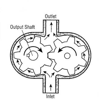
Graphic 1.
External gear motors have one
driven gear and one idler gear
enclosed in single housing.
Output torque is a function of
pressure on one tooth because
pressure on other teeth is in
hydraulic balance.
Internal Gear Motors
Internal gear motors fall into two categories. A direct-drive gear motor consists of an inner-outer gear set and an output shaft, Graphic 2. The inner gear has one less tooth than the outer. The shape of the teeth is such that all teeth of the inner gear are in contact with some portion of the outer gear at all times. When pressure fluid is introduced into the motor, both gears rotate. The motor housing has an integral kidney-shaped inlet and outlet ports. The centers of rotation of the two gears are separated by a given amount known as the eccentricity. The center of the inner gear coincides with the center of the output shaft.
In Graphic 2 (a), pressure fluid enters the motor through the inlet port. Because the inner gear has one less tooth than the outer, a pocket is formed between the inner teeth 6 and 1, and other socket A. The kidney-shaped inlet port is design so that just as this pockets volume reaches its maximum, fluid flow is shut off, with the tips of inner gear teeth 6 and 1 providing a seal, Graphic 2(b).
As the pair of inner and outer gears continues to rotate, Graphic 2(c), a new pocket is formed between inner teeth 6 and 5, and outer socket G. Meanwhile the pocket formed between inner teeth 6 and 1 and outer socket A has moved around opposite the kidney-shaped outlet port, steadily draining as the volume of the pocket decreases. The gradual, metered volume change of the pockets provides smooth, uniform fluid flow with a minimum of pressure variation (or ripple).
Because of the extra tooth in the outer gear, the inner gear teeth move ahead of the outer by one tooth per revolution. In Graphic 2(c), inner tooth 4 is seated in outer socket E. On the next cycle, inner tooth 4 will seat in outer socket F. This produces a low relative differential speed between the gears.
Orbiting Gerotor Motor
An orbiting Gerotor motor, Graphic 3, consists of a set of matched gears, a coupling, an output shaft, and commutator or valve plate. The stationary outer gear has one more tooth than the rotating inner gear. The commutator turns at the same rate as the inner gear and always provides pressure fluid and a passageway to tank to the proper spaces between the two gears.
In operation, Graphic 3(a), tooth 1 of the inner gear is aligned exactly in socket D of the outer gear. Point y is the center of the stationary gear, and point x is the center of the rotor. If there were no fluid, the rotor would be free to pivot about socket D in either direction. It could move toward seating tooth 2 in socket E or conversely, toward seating tooth 6 in socket J.
When pressure fluid flows into the lower half of the volume between the inner and outer gears, if a passageway to tank is provided for the upper-half volume between the inner and outer gears, a moment is induced which rotates the inner gear counterclockwise and starts to seat tooth 2 in socket E. Tooth 4, at the instant shown in Graphic 3(a), provides a seal between pressure and return fluid.
However, as rotation continues, the locus of point x is clockwise. As each succeeding tooth of the rotor seats in its socket, Graphic 3(b), the tooth directly opposite on the rotor from the seated tooth becomes the seal between pressure and return fluid. The pressurized fluid continues to force the rotor to mesh in a clockwise direction while it turns counterclockwise.
Because of the one extra socket in the fixed gear, the next time tooth 1 seats, it will be in socket J. At that point, the shaft has turned 1/7 of a revolution, and point x has moved 6/7 of its full circle. In Graphic 3(c), tooth 2 has mated with socket D, and point x has again become aligned between socket D and point y, indicating that the rotor has made one full revolution inside of the outer gear. Tooth 1 has moved through an angle of 60 from its original in Graphic 3(a); 42 (or 6x7) tooth engagements or fluids cycles would be needed for the shaft to complete one revolution.
The commutator or valve plate, shown in Graphic 3(d), (e), and (f), contains pressure and tank passages for each tooth of the rotor. The passages are spaced so they do not provide for pressure or return flow to the appropriate port as a tooth seats in its socket. At all other times, the passages are blocked or are providing pressure fluid or a tank passage in the appropriate half of the motor between gears.
Roller-Vane Gerotor Motor
A roller-vane Gerotor motor, Graphic 4, is a variation of the orbiting gerotor motor. It has a stationary ring gear (or stator) and a moving planet gear (or rotor). Instead of being held by two journal bearings, the eccentric arm of the planetary is held by meshing of the 6 tooth rotor and the 7 tooth socket stator. Instead of direct contact between the stator and rotor, roller vanes reduce wear, enabling the motors to be use in closed-loop, high pressure hydrostatic circuits as direct-mounted wheel drives.
Vane Motors
Vane motor, Graphic 5, have a slotted rotor mounted on a drive shaft that is driven by the rotor. Vanes, closely fitted into the rotor slots, move radially to seal against the cam ring. The ring has two major and two minor radial sections joined by transitional sections or ramps. These contours and the pressures introduced to them are balanced diametrically.
In some designs, light springs force the vanes radially against the cam contour to assure a seal at zero speed so the motor can develop starting torque. The springs are assisted by angular momentum at higher speeds. Radial grooves and holes through the vanes equalize radial hydraulic forces on the vanes at all times.
Pressure fluid enters and leaves the motor housing through openings in the side plates at the ramps. Pressure fluid entering at the inlet ports moves the rotor counterclockwise. The rotor transports the fluid to the ramp openings at the outlet ports to return to tank. If pressure were introduced at the outlet ports, it would turn the motor clockwise.
The rotor is separated axially from the side plate surfaces by the fluid film. The front side plate is clamped against the cam ring by pressure and maintains optimum clearances as temperature and pressure change dimensions.
Vane motors provide good operating efficiencies, but not as high as those of piston motors. However, vane motors generally cost less than piston motors of corresponding horsepower ratings.
The service life of a vane motor usually is shorter than that of a piston motor. Vane motors are available with displacements of 20 in.3/rev; some low-speed/high-torque models come with displacements to 756 in.3/rev. Except for the high-displacement, low-speed models, vane motors have limited low-speed capability.
Piston-Type Motors
Radial-Piston Motors, Graphic 6, have a cylinder barrel attached to a driven shaft; the barrel contains a number of pistons that reciprocate in radial bores. The outer piston ends bear against a thrust ring. Pressure fluid flows through a pintle in the center of the cylinder barrel to drive the pistons outward.
The pistons push against the thrust ring and the reaction forces rotate the barrel.
Motor displacement is varied by shifting the slide block laterally to change the piston stroke. When the centerlines of the cylinder barrel and housing coincide, there is no fluid flow and therefore the cylinder barrel stops. Moving the slide past center reverses direction of motor rotation.
Radial piston motors are very efficient. Although the high degree of precision required in the manufacture of radial piston motors raises initial costs, they generally have a long life. They provide high torque at relatively low shaft speeds and excellent low speed operation with high efficiency; they have limited high speed capabilities. Radial piston motors have displacements to 1000 in.3/rev.
Axial-piston motors also use the reciprocating piston motion principle to rotate the output shaft, but motion is axial, rather than radial. Their efficiency characteristics are similar to those of radial-piston motors. Initally, axial-piston motors cost more than vane or gear motors of comparable horsepower, and have a long operating life. Because of this, their higher initial cost may not truly reflect the expected overall costs during the life of a piece of equipment.
In general, axial-piston motors have excellent high speed capabilities, but unlike radial-piston motors, they are limited at low operating speeds; the inline type will operate down to 100rpm and the bent-axis type will give output down to the 4-rpm range. Axial piston motors are available with displacements from a fraction to 65 in.3/rev.
Inline-Piston Motors
Inline-piston motors, Graphic 7, generate torque through pressure exerted on the ends of pistons which reciprocate in a cylinder block. In the inline design, the motor drive-shaft and cylinder block are centered on the same axis. Pressure at the ends of the pistons causes a reaction against a tilted swashplate and rotates the cylinder block and motor shaft. Torque is proportional to the area of the pistons and is a function of the angle at which the swashplate is positioned.
The motors are built in fixed-and variable-displacement models. The swashplate angle determines motor displacement. In the variable model, the swashplate is mounted in a swinging yoke, and the angle can be changed by various means—ranging from a simple lever or hand-wheel to sophisticated servo controls. Increasing the swashplate angle increases the torque capacity but reduces drive shaft speed. Conversely, reducing the angle reduces the torque capacity but increases drive shaft speeds (unless fluid pressure decreases). Angle stops are included so that torque and speed stay within operating limits.
A compensator varies motor displacement in response to changes in the work load. A spring-loaded piston is connected to the yoke and moves it in response to variations in operating pressure. Any load increase is accompanied by a corresponding pressure increase as a result of the additional torque requirements. The control then automatically adjusts the yoke so that torque increases when the load is light. Ideally, the compensator regulates displacement for maximum performance under all load conditions up to relief valve setting.
Bent-Axis Piston Motors
Bent-axis piston motors, Graphic 8, develop torque through a reaction to pressure on reciprocating pistons. In this design, the cylinder block and drive shaft are mounted at an angle to each other; the reaction is against the drive-shaft flange.
Speed and torque change with changes in the angle—from a predetermined minimum speed with a maximum displacement and torque at an angle of approximately 30° to a maximum speed with a minimum displacement and torque at about 71/2°. Both fixed-and variable-displacement models are available.
Selecting a Hydraulic Motor
The application of the hydraulic motor generally dictates the required horsepower and motor speed range, although the actual speed and torque required may sometimes be varied while maintaining the required horsepower. The type of motor selected depends on the required reliability, life and performance.
Once the type of motor is determined, the selection of actual size is based on the expected life and the economics of the overall installation on the machine.
A fluid motor operating at less than rated capacity will provide a service life extension more than proportional to the reduction in operation below the rated capacity.
The maximum horsepower produce by a motor is reached when operating at the maximum system pressure and at the maximum shaft speed. If the motor is always to be operated under these conditions, its initial cost will be lowest. However, where output speed must be reduced, the overall cost of the motor with speed reduction must be considered—to optimize the overall drive installation costs.
Sizing Hydraulic Motors
As an example of how to calculate hydraulic motor size to match an application, consider the following: an application calls for 5hp at 3,000 rpm, with an available supply pressure of 3,000 psi, and return line pressure of 100 psi; the pressure differential is 2,900 psi.
Pressure in these equations is the difference between inlet and outlet pressure. Because of this, any pressure at the outlet port reduces torque output of the fluid motor.
The efficiency factor for most motors will be fairly constant when operating from half to full rated pressure, and over the middle portion of the rated speed range. As speed nears either extreme, efficiency decreases.
Lower operating pressures result in lower overall efficiencies because of fixed internal rotating losses that are characteristic of any fluid motor. Reducing displacement from maximum in variable-displacement motors also reduces the overall efficiency.
Hydraulic Motor Malfunctions
The majority of motor problems fall into these categories:
Improper fluid—The motor is no different than any other of the components of the hydraulic system—it must have clean fluid, in adequate supply, and of the proper quality and viscosity.
Poor Maintenance—A poor maintenance program runs a close second in the cause of major problems. Typical slips in the program include:
- Failure to check and repair lines and connections to stop leaks; faulty connections can allow dirt and air into the system, lower pressure, and cause erratic operation.
- Failure to install motor correctly. Motor shaft misalignment can cause bearing wear which can lead to lost efficiency. A misaligned shaft also can reduce torque, increase friction drag and heating, and also result in shaft failure.
- Failure to find the cause of a motor malfunction. If a motor fails, always look for the cause of the failure. Obviously, if the cause is not corrected, failure will recur.
Improper Operation—Exceeding a motor’s operating limits promotes motor failure. Every motor has design limitations on pressure, speed, torque, displacement, load and temperature. Excessive pressure can generate heat because of motor slippage, and can cause the motor to exceed torque limits. Excessive speed can cause heating and can cause wear of bearings and other internal parts.
Excessive torque can cause fatigue and stress to bearings and the motor shaft, especially on applications that require frequent motor reversing. Excessive load can create bearing and shaft fatigue. And finally, excessive temperature can cause loss of efficiency because oil becomes thinner, and can produce rapid wear due to lack of lubrication.
Source : http://www.cwu.edu/~cattinw/Courses/MET_310_Hydrualics_Pneumatics/Hydraulic%20Motors.doc
Web site link: http://www.cwu.edu/~cattinw/Courses
Google key word : Hydraulic motors file type : doc
Author : not indicated on the source document of the above text
If you are the author of the text above and you not agree to share your knowledge for teaching, research, scholarship (for fair use as indicated in the United States copyrigh low) please send us an e-mail and we will remove your text quickly.
Hydraulic motors
If you want to quickly find the pages about a particular topic as Hydraulic motors use the following search engine:
Hydraulic motors
Please visit our home page
Larapedia.com Terms of service and privacy page