Laboratory Instruments
Laboratory Instruments
The following texts are the property of their respective authors and we thank them for giving us the opportunity to share for free to students, teachers and users of the Web their texts will used only for illustrative educational and scientific purposes only.
All the information in our site are for educational uses.
The information of medicine and health contained in the site are of a general nature and purpose which is purely informative and for this reason may not replace in any case, the council of a doctor or a qualified entity legally to the profession.
Laboratory Instruments
RET
Lab 1. Introduction to Laboratory Instruments
Objectives:
- Study the safety procedures of the electrical lab
- Study the basic functions of digital multi-meter (DMM)
- Study common electronics laboratory instruments
- Principles of measuring voltage, current and resistance
- Build and analyze a simple electrical circuit
- Intro to Ohms Law
Equipment:
Digital Multi-meter
- Function Generator
- Oscilloscope
- Proto-board
- Assorted resistors and diodes
Procedure:
- Please read carefully the general safety procedures in the lab
- Voltage, Current and Resistance measurement
All multi-meters measure voltage, current and resistance. Some multi-meters measure additional electrical parameters.
- Voltage is measured in volts (V). You always measure a voltage change: i.e., the voltage difference between two points in a circuit.
- Current, measured in Amperes (A), is the net amount of electrical charge flowing past a point per second.
- Resistance, measured in Ohms (Ω), limits the flow of current.
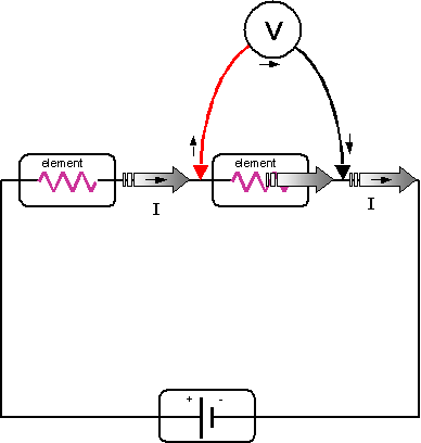
Measure Voltage in parallel
Notes:
-
Notice that some of the current flowing in the circuit actually flows through the voltmeter. This current must be very small in relation to the total circuit current I. Thus, the internal resistance of a voltmeter is very high.
-
A voltmeter measures a voltage change, which may be positive or negative. All voltmeters are designed to give a positive reading whenever the red probe is placed on the side of the circuit element that is closest to the positive pole of the battery. Red to positive.
-
Because the voltmeter is placed in parallel with the circuit element, you do not need to physically alter your circuit in order to measure voltage.
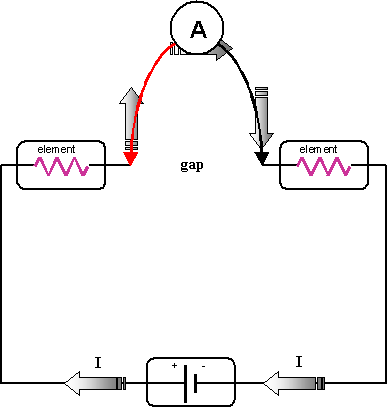
Measure Current in Series
To measure current through a particular loop of your circuit, connect the ammeter in series with the other elements in the circuit loop. This means you must physically modify your circuit in the following way:
-
Create a gap in the segment where you want to measure the current.
-
Reconnect the gap using your ammeter as a jumper wire
Notes:
-
You must be VERY careful to make sure that your multi-meter is configured correctly before placing it in parallel across a circuit element. Ammeters have very LOW internal resistance, and can be damaged when placed in parallel across circuit elements.
-
You can use the ammeter to measure the direction of current flow, provided to follow the convention of red to positive.
-
Because the ammeter is placed in series with the other circuit elements, you must physically alter your circuit in order to measure current with an ammeter.
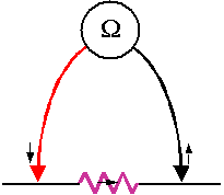
Measure Resistance
To measure resistance, select the ohms mode, remove the resistor to be measured from your circuit, and place the ohmmeter leads across the resistor leads. It is not OK to use your fingers to do this
Notes:
-
The Ohmmeter works by placing a small voltage across the circuit element. The current that flows through the element in response to that voltage determines the ohmmeter reading.
-
You cannot measure the resistance of a resistor while it is in a circuit - there may be many other current paths available, or the battery may force current backwards through the ohmmeter.
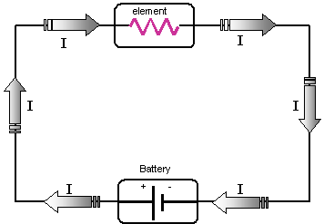
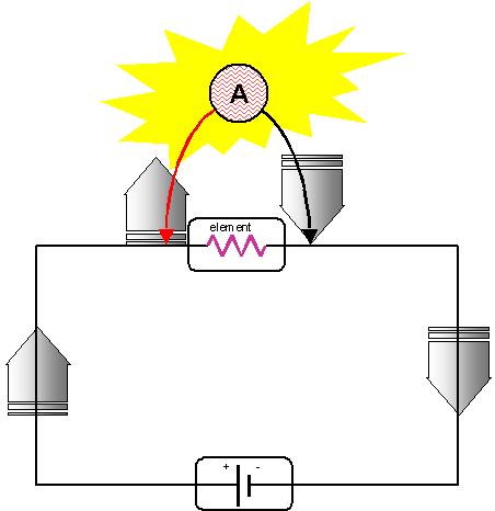
A Simple Electrical Circuit
Caution!! A Common Mistake
Study the diagram below very carefully. This is a very common mistake and it is very easy to do. A multi-meter configured as a current meter is placed in parallel across a source capable of supplying a significant amount of current - in this case the power supply. Because the ammeter has a very small internal resistance, the full current capability of the supply is delivered to the ammeter. This can easily destroy the meter, although most all meters have a fuse to protect the meter.
Ohms Law (general form):
E = I*R
where:
E = Energy or Voltage (Volts, V)
I = Current (Amps, A)
R = Resistance (Ohms, W)
Lab 1
Data Sheet
Name(s):
Measure Resistors
Nominal Value |
DMM Reading |
% Error Calculated |
|
|
|
|
|
|
|
|
|
In-circuit readings
Voltage (V) |
Current (I) |
Calculated Resistance (R) |
|
|
|
|
|
|
|
|
|
|
|
|
Compare Resistance Readings
DMM |
In-Circuit |
% Error calculated |
|
|
|
|
|
|
|
|
|
RET
Lab 2. Series and Parallel Circuits
Objectives:
- To study series and parallel circuits
- To further study Ohm’s Law
Equipment:
- Digital multi-meter
- Light bulbs
- Proto-Board
Procedure:
- Series circuit
Connect the following circuit. Use different types of bulbs if possible.
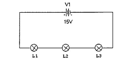
Figure 1. Series Circuit
Complete the attached table (round all numbers to be within two decimal places).
- Before turning the power on, measure the resistance of each bulb (Rc1, Rc2, and Rc3). Note that these are the resistance of the cold filaments.
- Set supply voltage to 15V and note in both tables.
- After turning on the power, measure the voltage across each of the bulbs (V1, V2, and V3).
- Measure the current flowing through the bulbs (I).
- Calculate the resistance of each of the bulbs (Rh1, Rh2, and Rh3) using your measured voltages and current. Again, note that these are the resistance of hot filaments.
- Calculate the power dissipated on each bulb (P1, P2, and P3).
Answer the following questions on the attached sheet:
- What should be the total resistance of the bulbs with hot filaments?
- What should be the current flowing through the battery or power supply?
- What should be the total power dissipated on all three bulbs?
- Is the resistance of a hot filament higher or lower than that of a cold filament?...why?
- Parallel circuit
Connect the following circuit.
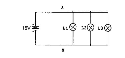
Figure 2. Parallel Circuit
Complete the attached table (round all numbers to be with two decimal places).
- When the power is on, measure the voltage across each bulb (V1, V2 and V3)
- Measure the current flowing through each bulb (I1, I2 and I3).
- Calculate the resistance of each of the bulbs (Rh1, Rh2, and Rh3) using your measured voltages and current. Again, note that these are the resistance of hot filaments.
- Calculate the power dissipated on each bulb (P1, P2, and P3).
Answer the following questions on the attached sheet:
i) What should be the total resistance of the bulbs with hot filaments?
ii) What should be the current flowing through the battery or power supply?
iii) What should be the total power dissipated on all three bulbs?
 Lab 2 Ohm’s Law and Simple Circuits
Assignment Page
Series Circuit Chart
Supply voltage: ___________________
Show your work below for the questions in Procedure # 1
Parallel Circuit Chart
Supply voltage: ___________________
Show your work below for the questions in Procedure # 2
|
L1 |
L2 |
L3 |
Rc (R) |
|
|
|
Voltage (E) |
|
|
|
Amps (I) |
|
|
|
Rh (R) |
|
|
|
P (W) |
|
|
|
|
L1 |
L2 |
L3 |
Rc (R) |
|
|
|
Voltage (E) |
|
|
|
Amps (I) |
|
|
|
Rh (R) |
|
|
|
P (W) |
|
|
|
RET
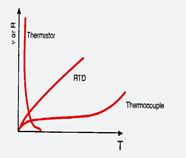
Lab 3. Thermistor
Objectives:
- To build a temperature sensor using a thermistor
- To study the procedures of thermistor calibration
- To study data analysis techniques
Equipment:
- Thermistor
- Lego brick
- Soldering equipement
- Thermometer
- Ice
- Heater box
Procedure:
- Build the temperature sensor using the procedure on the handouts
- Calibration of Thermistor
- Take RAW readings from the thermistor using the RCX at various temperatures
- Simultaneously measure the actual temperature
- Either use the following equation for thermistor calibration or use a spreadsheet such as Microsoft Excel to graph your data using a log-log scale and a regression equation. The following equation relates the logarithm of electrical resistance R to the Kelvin temperature T.
Steinhart-equation:
1/T = A + B ln R + C (lnR)3
R = resistance of thermistor (Ω)
T = ambient temperature in 0K
A, B & C = curve fitting constants
A, B and C are found by selecting three data points on the published data curve and solving the three simultaneous equations.
- Common thermistor curve
Temperature (°C) |
RCX reading |
|
|
|
RET
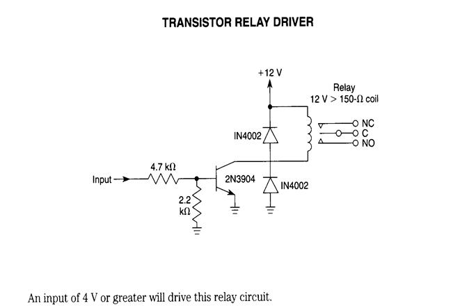
Lab 4. Relay temperature control circuit
Objectives:
1. To study the function of relays, transistors, and diodes
2. To design a relay circuit to control a heater device
Equipment:
1. RCX
2. Digital multi-meter
3. Breadboard or proto-board
4. Relays
5. Transistors
6. Resistors
7. Diodes
Procedure:
- Construct the following circuit on proto-board:
RET
Lab 5. Rectification circuit using diode and capacitor
Objectives:
- To study the rectification function of diodes
- To study the filtering function of capacitors
- Become familiar with laboratory instruments
Equipment:
- Digital oscilloscope, Agilent 54621-A
- Function generator
- Digital multi-meter
- Proto-board
- Resistors 1kΩ, 100Ω
- Capacitors, 1000μF
- Diodes 1N4001
Procedure:
- Function generator and oscilloscope
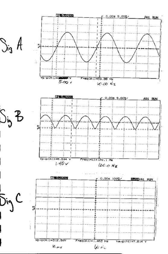
The instructor has connected channel 1 of the oscilloscope to the output of the function generator. After turning the power on, you should, on the oscilloscope, see a sinusoidal wave with frequency of 60hz, and amplitude of 10v, and zero DC offset generated by the function generator. This signal will be used as the input signal for both circuits you will test in this lab.
Follow the instructions of the instructor, adjust the oscilloscope and the function generator in order to study the functions.
- Rectification
Connect the following full-wave rectification circuit. Use the sinusoidal signal generated at step 1 as the input signal. Use a 1kΩ resistor as the load resistor.
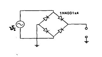
Monitor the input and output signals using the channel 1 of the oscilloscope. Due to the fact that these two signals do not have a common ground, you can only observe one signal at a time. What is the major difference between these two signals?
With the help of the instructor, connect the input and output signals to the digital oscilloscope. What is the major difference between the two signals?
- Filtering
Add an RC-filter to the rectification circuit as shown below. Monitor the input and output signals using the oscilloscope.
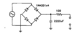
What is the major difference between the two signals? Based on the plots, comment on the effects of rectification and filtering.
Lab 3 Diode and Capacitor
Assignment Page
- What does signal “A” represent? In 3-4 sentences, describe the “A” signal and what is going on with it?
- What does signal “B” represent? In 3-4 sentences, describe the “B” signal and what is going on with it?
- What does signal “C” represent? In 3-4 sentences, describe the “C” signal and what is going on with it?
- Describe the differences and similarities between the 3 graphs.
RET
Lab 6. Distance Sensor
Objectives:
- Build the distance sensor circuit
- Calibrate the distance sensor
Equipment:
- Voltage regulator LM78L05
- Distance sensor GP2D12
- 9V battery
- 9V battery connectors
- Toggle switch
- Capacitors 0.1μF
- Resistors 1kΩ and 47kΩ
- Diodes 1N4148
- NTE 234 transistor
- RCX connector wire
- Proto-board
- Punchboard
- Soldering iron and solder
Procedure:
- Build the circuit
Build the following circuit on the breadboards by using the components and then solder on a punchboard:
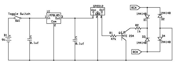
Figure1: Distance Sensor Circuit
- Test the Circuit by taking RAW readings using the RCX.
- Calibrate the sensor by recording RAW readings at various distances and graphing those readings in a spreadsheet such as Microsoft Excel. Then find a regression relationship between the RAW readings and the actual distance to find a formula to be used in your distance sensor program.
Example chart of readings:
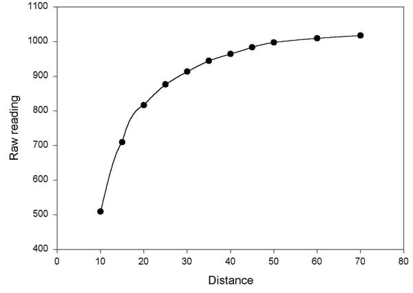
Figure2: Chart of distance versus RCX readings
Distance ( ) |
RCX reading |
|
|
|
RET
Lab 7. Color Sensor
Objectives:
- Build the color sensor circuit
- Calibrate the color sensor
Equipment:
- Color sensor components
- Breadboards
- Soldering iron and solder
Procedure:
- Build the circuit
Build the following circuit on the breadboards by using the components then solder on punchboards:
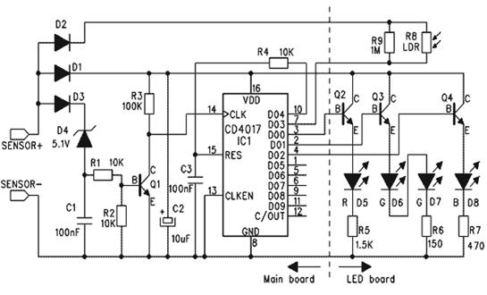
Figure1: Color sensor circuit
- Test the Circuit by taking RAW readings using the RCX.
- Calibrate the sensor by recording RAW readings for different known colors and relating those readings to a particular color in your program.
RET
Lab 8. Digital counter
Objectives:
1. Study a J-K flip-flop-based digital counter.
- Study BCD seven segment display decoder and 7-segment display.
- Study logic gates.
Equipment:
- Proto-board
- Digital multi-meter (DMM)
- Logic probe
- Common-anode 7-segment LED display, LR1737R
- BCD-to-seven-segment decoder/driver 7447
- Dual J-K negative-edge-triggered flip-flop 74112 (2)
- TTL logic gates, assorted
- Resistors, assorted
Procedure:
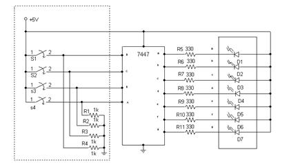
1. 7-segment display and its driver.
Connect a common-anode 7-segment LED display to a 7447 decoder/driver as shown in the following circuit schematic. Please note that the area contained in the dashed-lined box is the “DIP switch” section of the proto-board and you do not need to reconstruct it. To provide the A, B, C, and D pins of the 7447 decoder with binary-coded-decimal (BCD) inputs of 0000 to 1001 (0-9 decimal), you may set the slide switch to the +5V position, and set the DIP switches to upper or lower positions accordingly.
Make the right decimal point of the seven-segment display always lit. To do this, you need to connect pin 9 of the 7-segment display to ground through a 330Ω resistor.
Do not disassemble this circuit because you will need to use it at step 2.
- Use the DIP switch to provide BCD inputs of 0000 through 1001 (0-9 decimal). Verify that correct numbers are displayed.
- What are displayed when A, B, C, and D are set for hexadecimal values A through F (i.e. binary 1010 through 1111)?
2 Four-bit counter
Construct the following counter circuit using four JK flip-flops (two 74112). Connect this circuit to the BCD driver-display circuit you have constructed during step1, with the A, B, C, and D outputs replacing the DIP switches.
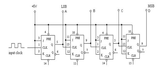
- Connect all four CLEAR inputs to a normally-high pushbutton. Connect the CLK input of the first JK flip-flop to another normally-high pushbutton. These pushbuttons will provide high-to-low transitions for the CLEAR and the CLK pins of 74112, which are needed to clear the output and to toggle the output, respectively.
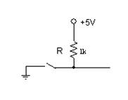
There are two pushbuttons on the protoboard and you can use them for this purpose. Make sure you understand the functions of the pushbuttons before connecting them into your circuit. The easiest way to check the functions is to use a multimeter to check the connectivity at each position of the pushbutton. Your normally-high pushbuttons may be built using the following diagram.
- Clear the counter by pushing the CLEAR pushbutton.
- Push the CLK pushbutton. Observe the display changes each time the button is pushed. Note that the pushbutton sometimes does not provide a clear-cut high-to-low transition due to switch rebounce. As a result, you may observe sluggish responses or multiple jumps of the display.
- Draw a timing diagram, including at least 10 clock cycles, to show the states of the CLK input and the A, B, C, and D outputs.
- Use a function generator on the proto-board to generate a TTL signal with a period of 0.5 sec. Use this signal as the clock input to the counter. Your digital display should show sequential increment from 0 to 9, followed by unrecognizable displays of hex numbers A through F. The display should then go back to 0 and repeat the above sequence. Demonstrate the function of your circuit to the instructor.
- Design a logic circuit to make the counter display automatically return to 0 after displaying decimal 9. Try to make your logic design simple. Find the logic gates you need in the storage area of Room 134B. Insert this circuit into the counter circuit you have built. Test your circuit and demonstrate the results to your instructor.
- Increase the frequency of the clock signal and observe the display change. How fast can you update the display?
Keys to success for this lab: Patience and Neatness.
Source : http://chert.cis.ksu.edu/ret-site/examples/labs/Labs.doc
Web site link to visit : http://chert.cis.ksu.edu/ret-site/examples/labs/index.html
Google key word : Laboratory Instruments file type : doc
Author : not indicated on the source document of the above text
If you are the author of the text above and you not agree to share your knowledge for teaching, research, scholarship (for fair use as indicated in the United States copyrigh low) please send us an e-mail and we will remove your text quickly.
Laboratory Instruments
If you want to quickly find the pages about a particular topic as Laboratory Instruments use the following search engine:
Laboratory Instruments
Please visit our home page
Larapedia.com Terms of service and privacy page