Geometric Dimensioning & Tolerancing in engineering drawings
Geometric Dimensioning & Tolerancing in engineering drawings
The following texts are the property of their respective authors and we thank them for giving us the opportunity to share for free to students, teachers and users of the Web their texts will used only for illustrative educational and scientific purposes only.
All the information in our site are given for nonprofit educational purposes
The information of medicine and health contained in the site are of a general nature and purpose which is purely informative and for this reason may not replace in any case, the council of a doctor or a qualified entity legally to the profession.
Geometric Dimensioning & Tolerancing in engineering drawings
Introduction: The purpose of this unit is to give an introduction to the topic of geometric dimensioning and tolerancing. With the increase of interchangeable manufacturing where companies are producing parts all over the world, it is necessary to produce drawings where nothing is left to interpretation. Geometric dimensioning and tolerancing, when applied appropriately, leaves little room for interpretation. It allows for consistency between design, manufacturing, and inspection. The standard that specifies correct practices for dimensioning and tolerancing is ASME Y14.5M. This unit will cover terminology used in geometric dimensioning and tolerancing, method for reading feature control frames, datum reference frame theory, and explanations of each geometric characteristic.
Explain the following:
Geometric Dimensioning and Tolerancing is a three-dimensional, mathematical system. Within this system, features on an object are oriented or located relative to a Cartesian Coordinate System or Datum Reference Frame. This is done using Feature Control Frames, which specify acceptable tolerance zones for the features relative to the Datum Reference Frame.
- Explain the following terms related to the Datum Reference Frame:
- Datum Reference Frame - Sufficient datum features, those most important to the design of a part, or designated portions of these features are chosen to position the part in relation to a set of three mutually perpendicular planes, jointly called a datum reference frame. The datum reference frame exists in theory only and not on the part: R2(250-251), R3(200-204).
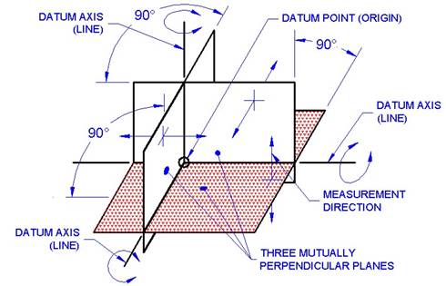
Figure 1. Datum Reference Frame.
2. Datum - A theoretically exact point, axis, or plane derived from the true geometric counterpart of a specified datum feature. A datum is the origin from which the location or geometric characteristics of features of a part are established.
3. Datum feature - An actual feature of a part that is used to establish a datum.
4. Datum Feature Symbol - The datum feature symbol is the symbolic means of indicating a datum feature and consists of a capital letter enclosed in a square frame and a leader line extending from the frame to the concerned feature, terminating with a triangle.
a. Applying a feature control frame to a feature without size such as a surface.
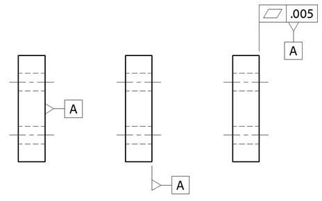
Figure 2. Applying a Feature Control Frame to a Feature Without Size.
b. Applying a feature control frame to a feature of size such as a hole, cylinder or slot. Datum B is the axis of the .498-.500 hole, datum C is the median plane of the .375-.380 slot, and datum D is the axis of the .997-1.000 cylinder.
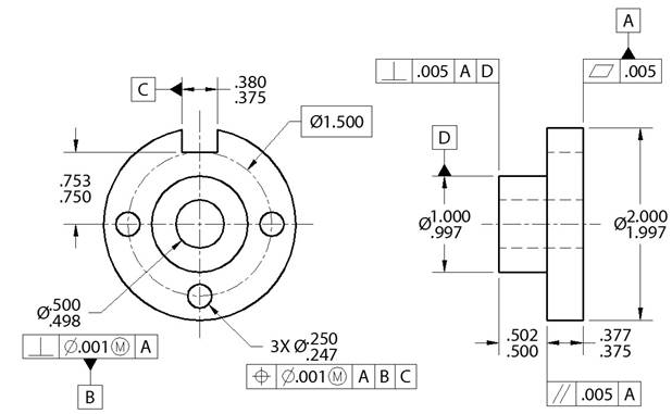
Figure 3. Applying a Feature Control Frame to a Feature With Size.
5. Datum feature simulator - A surface of adequately precise form contacting the datum feature(s) and used to establish the simulated datum(s). Typically this surface must be at least 10 times better in quality (flatness) than the tolerances specified on the drawing.
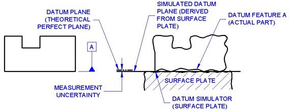
Figure 4. Datum Terminology.
4. Feature - The general term applied to a physical portion of a part, such as a surface, pin, tab, hole, or slot.
- Feature of size (feature with size) - A feature of size is a cylindrical or spherical surface, or a set of two opposed elements or opposed parallel surfaces, associated with a size dimension.
- Feature without size - Typically this is a planar surface.
- Types of Geometric Tolerances. A Geometric tolerance is the maximum permissible variation of form, profile, orientation, location, and runout from that indicated or specified on the drawing R1(340), R2(250).
Identify and describe the following:
- Straightness - Form tolerance where an element of a surface or a centerline is a straight line. Each longitudinal element on the surface must lie between two parallel lines. The shape of the tolerance zone is a 2D area between two parallel lines. R1(346-347), R2(253).
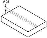
Figure 5. Straightness.
- Flatness - Form tolerance in which all surface elements are in one plane. All points on the surface must lie between two parallel planes. The shape of the tolerance zone is a 3D area between two parallel planes. R1(346-347), R2(255).
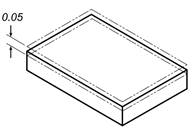
Figure 6. Flatness.
- Circularity (Roundness) - Form tolerance specifying a tolerance zone bounded by two concentric circles within which each circular element of a surface must lie. All points on the surface must lie between two concentric circles. The shape of the tolerance zone is a 2D area between two concentric circles. R1(346-347), R2(253-254).
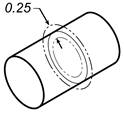
Figure 7. Circularity.
- Cylindricity - Form tolerance of a surface of revolution in which all points of the surface are equidistant from a common axis. All points on the surface must lie between two concentric cylinders. The shape of the tolerance zone is a 3D area between two concentric cylinders. R1(346-347), R2(255-256).
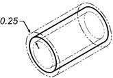
Figure 8. Cylindricity.
- Profile - A profile tolerance is the outline of an object in a given plane. Profiles are formed by projecting a three-dimensional figure onto a plane or by taking cross sections through the figure. R1(346-348), R2(253-256).
- Profile of a Line - Each point on the specified path must lie between two parallel contours. The shape of the tolerance zone is a 2D area between the two contours. Perfect geometry is located with basic dimensions.
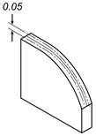
Figure 9. Profile of a Line.
- Profile of a Surface - Each point on the surface must lay between two parallel/ concentric contours. The shape of the tolerance zone is a 3D area between the two contours. Perfect geometry is located with basic dimensions.
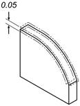
Figure 10. Profile of a Surface.
- Parallelism - Orientation tolerance of a surface or center plane, equidistant at all points from a datum plane; or an axis, equidistant along its length from one or more datum planes or a datum axis. All points on the surface must lie between two parallel planes. The shape of the tolerance zone is a 3D area between two parallel planes. R1(349), R2(255).
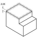
Figure 11. Parallelism.
- Angularity - Orientation tolerance of a surface, center plane, or axis at a specified angle (other than 90º) from a datum plane or axis. All points on the surface must lie between two parallel planes. Perfect geometry is located using basic dimensions. The shape of the tolerance zone is a 3D area between two parallel planes. R1(349), R2(255-256).
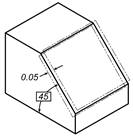
Figure 12. Angularity.
- Perpendicularity - Orientation tolerance of a surface, center plane, or axis at a right angle to a datum plane or axis. All points on the surface must lie between two parallel planes. The shape of the tolerance zone is a 3D area between two parallel planes. R1(349-350), R2(255-256).
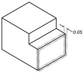
Figure 13. Perpendicularity.
- Runout - Runout is a composite tolerance used to control the functional relationship of one or more features of a part to a datum axis. R2(253-256).
- Circular Runout - All points on the surface must lie between two concentric circles relative to the datum feature. The shape of the tolerance zone is the 2D area between the two concentric circles.
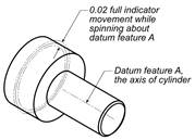
Figure 14. Circular Runout.
- Total Runout - All points on the surface must lie between two concentric cylinders relative to the datum feature. The shape of the tolerance zone is the 3D area between the two concentric cylinders.
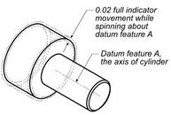
Figure 15. Total Runout.
- Concentricity - Location tolerance where the median points of all diametrically opposed elements of a figure of revolution are congruent with the axis of a datum feature. All points on the axis must lie within a cylinder relative to the datum axis. The shape of the tolerance zone is a 3D area within the cylinder. R1(351), R2(257-259).
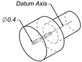
Figure 16. Concentricity.
Position - Location tolerance which defines a zone within which the center, axis, or center plane of a feature of size is permitted to vary from a true position. All points on the axis must lie within a cylinder. The cylinder is located with basic dimensions from the datums. The shape of the tolerance
- zone is a 3D area within the cylinder. R1(342-346), R2(257-259-Figure in book is incorrect).
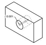
Figure 17. Position.
Define the following terms:
- Basic Dimension - A numerical value used to describe the theoretically exact size, profile, orientation, or location of a feature or datum target. Basic dimensions are enclosed within a rectangular frame. R1(341).
- Material Condition Modifiers R1(344-346).
- Maximum material condition - The condition in which a feature of size contains the maximum amount of material within the stated limits of size - for example, minimum hole diameter, maximum shaft diameter.
- Least material condition - The condition in which a feature of size contains the least amount of material within the stated limits of size - for example, the maximum hole diameter, minimum shaft diameter.
- Regardless of feature size - The geometric tolerance value is the same no matter what the size of the feature.
Identify and describe the make-up of a feature control frame. R1(340-341), R2(252).
- Sentence structure for given feature control frames.
- Frame for the geometric characteristic symbol.
- Frame for the zone descriptor, feature tolerance and material condition modifier.
- Frames for the primary, secondary and tertiary datum references.
- Between points identifying under feature control frame.
- Reading feature control frames.
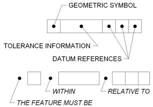
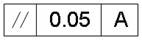
Figure 18. Reading a Feature Control Frame.
- The feature must be parallel within a five-hundredths of a millimeter tolerance zone relative to datum feature A.
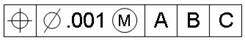
- The feature must be positioned within a one-thousandth of an inch cylindrical tolerance zone at maximum material condition relative to primary datum feature A, secondary datum feature B, and tertiary datum feature C.
Identify the symbols representing the following (see Table 1 for correct geometric characteristic symbols): R1(340), R2(252).
- Straightness.
- Flatness.
- Circularity (Roundness).
- Cylindricity.
- Profile of a Line.
- Profile of a Surface.
- Angularity.
- Perpendicularity.
- Parallelism.
- Position.
- Concentricity.
- Symmetry.
- Circular Runout.
- Total Runout.
- Maximum Material Condition.

- Least Material Condition.

- Diameter.

- Between.

- Basic Dimension.
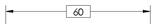
Table 1. Geometric Characteristic Symbols.
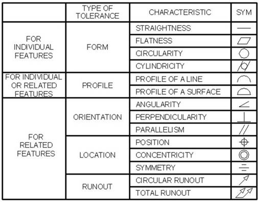
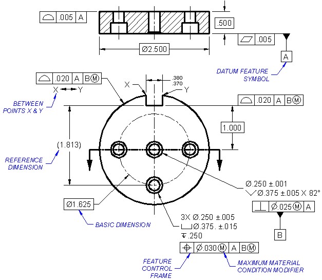
Figure 19. Common Symbols used with Geometric Dimensioning.
Source : http://www.waynecountyschools.org/cms/lib6/NC01000512/Centricity/Domain/2600/D3%20Basic%20Geometric%20Dimensioning%20and%20Tolerancing.doc
Web site link to visit: http://www.waynecountyschools.org
Google key word : Geometric Dimensioning & Tolerancing in engineering drawings file type : doc
Author : not indicated on the source document of the above text
If you are the author of the text above and you not agree to share your knowledge for teaching, research, scholarship (for fair use as indicated in the United States copyrigh low) please send us an e-mail and we will remove your text quickly.
Geometric Dimensioning & Tolerancing in engineering drawings
If you want to quickly find the pages about a particular topic as Geometric Dimensioning & Tolerancing in engineering drawings use the following search engine:
Geometric Dimensioning & Tolerancing in engineering drawings
Please visit our home page
Larapedia.com Terms of service and privacy page