Mechanical Properties of Materials
Mechanical Properties of Materials
The following texts are the property of their respective authors and we thank them for giving us the opportunity to share for free to students, teachers and users of the Web their texts will used only for illustrative educational and scientific purposes only.
All the information in our site are given for nonprofit educational purposes
The information of medicine and health contained in the site are of a general nature and purpose which is purely informative and for this reason may not replace in any case, the council of a doctor or a qualified entity legally to the profession.
Mechanical Properties of Materials
- Mechanical Properties of Materials
Once the important physical properties of a material have been established, mechanical properties such as yield strength and hardness must be considered. Mechanical properties are structure‑ sensitive in the sense that they depend upon the type of crystal structure and its bonding forces, and especially upon the nature and behavior of the imperfections that exist within the crystal itself or at the grain boundaries. Mechanical properties are important in processes that employ plastic deformation such as forming of bulk or sheet, as well as machining. Modulus of elasticity is also important in assembly.
An important characteristic that distinguishes metals from other materials is their ductility and ability to be deformed plastically without loss in strength. In design, 5 to 15 percent elongation provides the capacity to withstand sudden dynamic overloads. In order to accommodate such loads without failure, materials need dynamic toughness, high moduli of elasticity, and the ability to dissipate energy by substantial plastic deformation prior to fracture.
To predict the behavior of a material under load, engineers require reliable data on the mechanical properties of materials. Handbook data is available for the average properties of common alloys at 68°F. In design, the most frequently needed data are tensile yield strength, hardness, modulus of elasticity, and yield strengths at temperatures other than 68°F. Designers less frequently use resistance to creep, notch sensitivity, impact strength, and fatigue strength. Suppliers' catalogs frequently give more recent or complete data.
Production‑engineering data that is seldom found in handbooks include strength‑to‑weight ratios, cost per unit volume, and resistance to specific service environments.
A brief review of the major mechanical properties and their significance to design is included to ensure that the reader is familiar with the important aspects of each test.
4.4.1 Tensile Properties of Materials
When a material is subjected to a tensile or compressive load of sufficient magnitude, it will deform, at first elastically and then plastically. The deformation is elastic if after the load is removed the material returns to its original shape and dimensions; if it does not, the material has undergone plastic in addition to elastic deformation. The engineering stress‑strain diagram presents the elastic data for a material, whereas the natural (or true) stress‑strain diagram can present both elastic and plastic properties in a form that is useful to the designer and the engineer.
Engineering Stress-Strain Relationships
In the elastic range, deformation is proportional to the load that causes it. The proportionality is stated by Hooke's law in terms of the stress S and strain e:
 (4.1)
(4.1)
where E is Young's modulus, the constant of proportionality between stress and strain, lb/in.2, S is the stress = P/A = load/initial cross‑sectional area, lb/in.2, e is the engineering strain = Dl/l0 = change in length/original length, in./in.
If, in the process of pulling a tensile specimen to failure, the stress is plotted as a function of the strain at selected strains, the engineering stress‑strain curve results (Fig. 4.15). Note that the stress is plotted as a function of the strain, contrary to the usual procedure of plotting the dependent variable as a function of the independent variable.
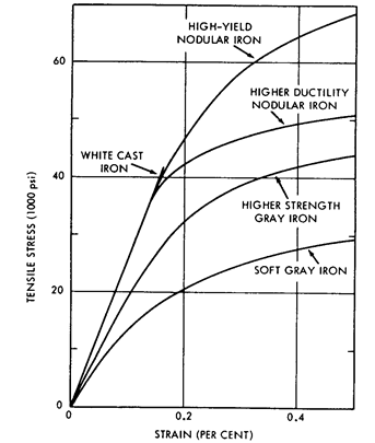
Figure 4.15 Stress-strain relationships of the principal cast irons in tension.
The straight part of the stress‑strain curve is the proportional range described by Hooke's law. The upper limit L of this range is known as the proportional limit. In the case of annealed low‑carbon steel there follows a region, the yield point, where the strain increases without any significant increase in stress. As indicated in the diagram, there can be an upper yield point, UY, and a lower yield point, LY. The maximum stress to which a material may be subjected is labeled U and the breaking point is denoted by B.
When a material is stressed beyond the elastic limit a permanent deformation results. However, this permanent deformation is associated with an elastic one. Notice that if the material of Fig. 4.15 is stressed to point P. upon the removal of the load so that the stress returns to zero, the plastic (permanent) strain is obtained by following downward from point P along a line parallel to the proportional line. Here we have at point P the total strain et, composed of an elastic component ee and a plastic one ep.
The area under the curve in Fig. 4.15, up to the proportional limit, represents the potential energy per unit volume (resilience) stored in an elastically deformed body; on the other hand, the total area under the curve up to point B represents the total energy per unit volume (modulus of toughness) required to break the specimen.
The engineering properties of commercial plastics vary considerably. For any given plastic, the stress‑strain curve depends upon both the temperature and the rate of strain. Slow straining and higher temperatures result in larger ultimate elongations and lower moduli (slopes). Figure 4.16 illustrates typical load‑elongation curves for three classes of plastics. Those plastics characterized by curve C have a high initial modulus and a small area under the stress‑strain curve (they are brittle). These plastics characteristically fail by catastrophic crack propagation at strains of about 2 percent.
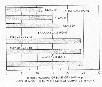
Figure 4.16 Tensile modulus of elasticity (million lb/in2) (secant modulus of 25 percent of ultimate strength).
Those plastics following curve B are usually referred to as engineering thermoplastics. These plastics have good tensile strength and hardness and will deform or draw beyond the yield point, which is evidence of much molecular orientation prior to failure. Thus, these plastics have impact resistance or toughness as well as good strength. They will withstand shock without brittle failure.
Curve A illustrates those plastics that are both tough and flexible. In these plastics, ductile deformation results from converting a material of low crystallinity to one of high crystallinity. These plastics have low tensile strength and moduli. The reader should understand that polymers are much more sensitive to temperature than either metals or ceramics in connection with their response to an applied stress. Figure 4.17 illustrates the relationship between temperature and elastic modulus of a typical thermoplastic material.
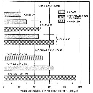
Figure 4.17 Yield strength, 0.2 percent offset (1000 lb/in2)
Natural (True) Stress-Strain Relationships
In many engineering designs, only the elastic behavior of a material is significant, so the engineering stress‑strain curve was commonly used to depict the behavior of a material up to its yield point. The yield strength of a material is calculated by dividing the load at the yield point by the original cross‑sectional area of the test specimen. However, when dealing with a material that is stressed beyond the elastic range, as in plasticity or metal forming, it is apparent that we should find a way to define the relationships in terms of the changing cross‑sectional area. This is a considerably more accurate way to obtain property information. Thus, the natural or true stress, s, is defined as the load at any instant divided by the cross‑sectional area at that instant. Thus,
 (4.2)
(4.2)
Source : http://www.ise.ncsu.edu/wysk/pictures/Chapter%204.doc
Web site link to visit: http://www.ise.ncsu.edu
Google key word : Mechanical Properties of Materials file type : doc
Author : not indicated on the source document of the above text
If you are the author of the text above and you not agree to share your knowledge for teaching, research, scholarship (for fair use as indicated in the United States copyrigh low) please send us an e-mail and we will remove your text quickly.
Mechanical Properties of Materials
If you want to quickly find the pages about a particular topic as Mechanical Properties of Materials use the following search engine:
Mechanical Properties of Materials
Please visit our home page
Larapedia.com Terms of service and privacy page