screws and nomenclature of thread technical drawing
screws and nomenclature of thread technical drawing
The following texts are the property of their respective authors and we thank them for giving us the opportunity to share for free to students, teachers and users of the Web their texts will used only for illustrative educational and scientific purposes only.
All the information in our site are given for nonprofit educational purposes
The information of medicine and health contained in the site are of a general nature and purpose which is purely informative and for this reason may not replace in any case, the council of a doctor or a qualified entity legally to the profession.
screws and nomenclature of thread technical drawing
Screws
Introduction
A machine element used for holding or joining two or more parts of a machine or structure is known as a fastener. The process of joining the parts is called fastening.
The fasteners are of two types:
- Permanent Screwed fasteners such as bolts, studs and nuts in combination, machine screws, set screws, etc., and keys, cotters, couplings, etc., are used for fastening components that require frequent assembly and disassembly.
- Removable (temporary): Riveting and welding processes are used for fastening permanently. Screwed fasteners occupy the most prominent place among the removable fasteners.
In general, screwed fasteners are used:
(i) Hold parts together,
(ii) Adjust parts with reference to each other and
(iii) Transmit power.
Nomenclature of Thread
A screw thread is obtained by cutting a continuous helical groove on a cylindrical surface (external thread). The threaded portion engages with a corresponding threaded hole (internal thread); forming a screwed fastener. Following are the terms that are associated with screw threads
Screw thread nomenclature
1. Major (nominal) diameter This is the largest diameter of a screw thread, touching the crests on an external thread or the roots of an internal thread.
2. Minor (core) diameter This is the smallest diameter of a screw thread, touching the roots or core of an external thread (root or core diameter) or the crests of an internal thread.
3. Pitch diameter This is the diameter of an imaginary cylinder, passing through the threads at the points where the thread width is equal to the space between threads
4. Pitch It is the distance measured parallel to the axis, between corresponding points on adjacent screw
threads.
5. Lead It is the distance a screw advances axially in one turn.
6. Flank Flank is the straight portion of the surface, on either side of the screw thread.
7. Crest It is the peak edge of a screw thread, that connects the adjacent flanks at the top.
8. Root It is the bottom edge of the thread that connects the adjacent flanks at the bottom.
9. Thread angle This is the angle included between the flanks of the thread, measured in an axial plane.
Forms of threads
Bureau of Indian Standards (BIS) adapts ISO (International Organisation for Standards) metric threads, which are adapted by a number of countries apart from India. The design profiles of external and internal threads. The following are the relations between the various parameters marked in the figure
Internal thread diameters External thread diameters
D - Major diameter d - Major diameter
D2 - Pitch diameter d2 - Pitch diameter
D1 - Minor diameter d3 - Minor diameter
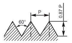
Metric screw threads
P = Pitch d3 = d2 – 2 (H/2 – H/6)
H = 0.86P = d – 1.22P
D = d = Major diameter H1 = (D – D1)/2 = 5H/8 = 0.54P
D2 = d2 = d – 0.75H h3 = (d – d3)/2 = 17/24H = 0.61P
D1 = d2 – 2(H/2 – H/4) = d – 2H1 R = H/6 = 0.14P = d – 1.08P
 Apart from ISO metric screw thread profile, there are other profiles in use to meet various applications. These profiles are shown in Fig. 5.3, the characteristics and applications of which are discussed below:
V- thread (sharp)This thread profile has a larger contact area, providing more frictional resistance to motion. Hence, it is used where effective positioning is required. It is also used in brass pipe work.
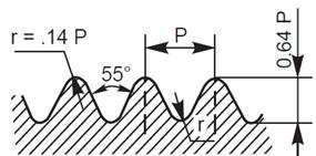
British Standard with worth (B.S .W) thread
This thread form is adopted in Britain in inch units. The profile has rounded ends, making it less liable to damage than sharp V-thread.
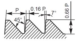
Buttress Thread
This thread is a combination of V-and square threads. It exhibits the advantages of square thread, like the ability to transmit power and low frictional resistance, with the strength of the V-thread. It is used where power transmission takes place in one direction only such as screw press, quick acting carpenter’s vice, etc.
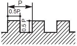
Square thread
Square thread is an ideal thread form for power transmission. In this, as the thread flank is at right angle to the axis, the normal force between the threads, acts parallel to the axis, with zero radial components. This enables the nut to transmit very high pressures, as in the case of a screw jack and other similar applications.
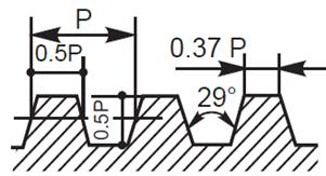
ACME Thread
It is a modified form of square thread. It is much stronger than square thread because of the wider base and it is easy to cut. The inclined sides of the thread facilitate quick and easy engagement and disengagement as for example, the split nut with the lead screw of a lathe.
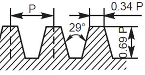
Worm Thread
Worm thread is similar to the ACME thread, but is deeper. It is used on shafts to carry power to worm wheels.
Forms of threads
Internal thread diameters External thread diameters
D - Major diameter d - Major diameter
D2 - Pitch diameter d2 - Pitch diameter
D1 - Minor diameter d3 - Minor diameter
Metric screw threads
P = Pitch
H = 0.86P
D = d = Major diameter
D2 = d2 = d – 0.75H
D1 = d2 – 2(H/2 – H/4) = d – 2H1
d3 = d2 – 2 (H/2 – H/6)
= d – 1.22P
H1 = (D – D1)/2 = 5H/8 = 0.54P
h3 = (d – d3)/2 = 17/24H = 0.61P
R = H/6 = 0.14P = d – 1.08P
Source : http://www.ise.ncsu.edu/wysk/pictures/Chapter%204.doc
Web site link to visit: http://www.ise.ncsu.edu
Google key word : screws and nomenclature of thread technical drawing file type : doc
Author : not indicated on the source document of the above text
If you are the author of the text above and you not agree to share your knowledge for teaching, research, scholarship (for fair use as indicated in the United States copyrigh low) please send us an e-mail and we will remove your text quickly.
screws and nomenclature of thread technical drawing
If you want to quickly find the pages about a particular topic as screws and nomenclature of thread technical drawing use the following search engine:
screws and nomenclature of thread technical drawing
Please visit our home page
Larapedia.com Terms of service and privacy page